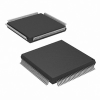
HSP50214BVIZ Intersil, HSP50214BVIZ Datasheet - Page 41

HSP50214BVIZ
Manufacturer Part Number
HSP50214BVIZ
Description
IC DOWNCONVERTER 14BIT 120-MQFP
Manufacturer
Intersil
Datasheet
1.HSP50214BVCZ.pdf
(62 pages)
Specifications of HSP50214BVIZ
Function
Downconverter
Rf Type
AMPS, CDMA, GSM, TDMA
Package / Case
120-MQFP, 120-PQFP
Lead Free Status / RoHS Status
Lead free / RoHS Compliant
Available stocks
Company
Part Number
Manufacturer
Quantity
Price
Company:
Part Number:
HSP50214BVIZ
Manufacturer:
HONGFA
Quantity:
30 000
Part Number:
HSP50214BVIZ
Manufacturer:
INTERSIL
Quantity:
20 000
Snap Shot Operation
The snapshot mode takes sets of adjacent samples at
programmed intervals. It is provided for tracking algorithms
that do not require processing of every sample, but do
require sets of adjacent samples. For example, bit sync
algorithms have narrow loop bandwidths that may not need
to be updated every sample. Computing the bit phase may
require 4 adjacent samples at 2 times the baud rate. The
snapshot mode allows the processor to implement the
tracking algorithms for high speed data without having to
handle every data sample.
The interval from the start of one snapshot to the start of a
second snapshot is programmed into bits 11-4 (where bit 11
is the MSB) of Control Word 21. The actual interval is the
CONTROL
WORD 23
A(2:0)
DATA
NEW
RD
|r|
Q
φ
ƒ
I
SEQUENCER
WRITE
16
16
16
16
16
0: I;Q (2’s COMP)
1: |r|;
2:
4: INPUT AGC (O; UNSIGNED BINARY)
5: AGC; TIMING (O; UNSIGNED BINARY;
ADDRESS “5”
ƒ
WRITE
(2’s COMPLEMENT)
φ
(R/
(I/Q SELECTED)
(O; UNSIGNED BINARY; 2’s COMP)
FIGURE 41. 8-BIT MICROPROCESSOR INTERFACE BUFFER RAM MODE BLOCK DIAGRAM
φ
SELECTED)
SNAPSHOT
WRITES TO
“SET OF WORDS”
INCR
WR
PROCCLK
DATARDY
DATARDY
SEQUENCER
INTRRP
ADDRESS
2’s COMP)
41
DUAL
PORT
RAM
R2, R1, R0
A2, A1, A0
RAM
INCR
RD
I/Q
STATUS
I
Q
|r|
φ
ƒ
0
1
2
3
4
R1
R/
DELAY TO DATARDY DEPENDS ON LENGTH OF FIR IF FREQ CHOSEN
I
φ
R0
FIGURE 42. RAM LOAD SEQUENCE
INT(22:16)
INT(15:0)
A1
TIMING
0
Q
AGC
1
A0
R2
HSP50214B
MSByte
R
0
1
2
3
R0 A1
LSByte
0
1
φ
A2
0
1
value programmed plus 1. If bits 11-4 = 11111111, then the
interval is set to 256. If sample sets are to be taken every 4
samples, then bits 11-4 = 00000011.
Figure 43 shows the relationship between the snapshot
samples and the snapshot interval.
A1
ƒ
A0
0
# SAMPLES = 4
1
OUTPUT
DATA
FIGURE 43. SNAP SHOT SAMPLING
ADJACENT
2
SAMPLES
INTERVAL = 64
3
R2 R1 R0 A2 A1 A0 SELECTION
X
0
0
0
0
0
0
0
0
0
0
0
1
1
1
1
1
1
1
1
4
X
0
0
0
0
0
0
0
0
1
1
1
0
0
0
0
0
0
0
1
0
0
0
0
1
1
1
1
0
0
1
0
0
0
1
1
1
1
X
X
X
X
0
0
0
0
0
0
0
0
0
0
0
0
0
0
0
0
0
1
X
X
0
0
1
1
0
0
1
1
0
0
0
0
1
0
0
1
1
1
0 RAM I LSB
1 RAM I MSB
0 RAM Q LSB
1 RAM Q MSB
0 RAM |r| LSB
1 RAM |r| MSB
0 RAM φ LSB
1 RAM φ MSB
0 RAM ƒ LSB
1 RAM ƒ MSB
X NOT USED
0 INPUT INTEG LSB
1 INPUT INTEG NMSB
0 INPUT INTEG MSB
0 AGC LSB
1 AGC MSB
0 TIMING LSB
1 TIMING MSB
X NOT USED
1 STATUS
62
63
64
May 1, 2007
FN4450.4
65


