APGAC031 Microchip Technology, APGAC031 Datasheet - Page 6
APGAC031
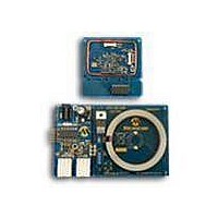
Manufacturer Part Number
APGAC031
Description
KIT ACC TIRE PRESSURE MON SYSTEM
Manufacturer
Microchip Technology
Type
Automotive, Tire Pressure Monitorr
Datasheet
1.APGAC031.pdf
(12 pages)
Specifications of APGAC031
Frequency
315MHz
Processor To Be Evaluated
PIC18F2680
Lead Free Status / RoHS Status
Lead free / RoHS Compliant
For Use With/related Products
APGRD003
Lead Free Status / Rohs Status
Lead free / RoHS Compliant


AN238
LF Commander
THEORY OF OPERATION
The system proposed in this document is based on an
auto-location system, enabling it to detect the position
of a specific S/TX device. This requires a LF
commander device at each wheel arc and possibly at
the spare tire mounting position.
Having a handheld LF commander unit can enable a
lower cost system. Although, this would require that the
system be manually relearned after a tire rotation, the
S/TX device is able to detect tire rotation or some other
system to engage data transmission. The LF
commander device is capable of sending commands to
the S/TX device via a LF transmission such as:
• Enable RF transmissions
• Disable RF transmissions
• Transmit an immediate message
• Transmit at 60-second intervals
• Transmit at 15-second intervals
• Transmit at 5-second intervals
The LF commander unit is based on the PIC16F628
MCU
commander and the S/TX is accomplished via
magnetic field. When the LF commander is transmitting
a message, it is essentially creating a magnetic field by
exciting a series LC circuit. The LC circuit is excited by
the PIC
to generate a 50% duty cycle at 125 kHz. The com-
mand data is then modulated on this 125 kHz signal in
the form of ASK modulation. Functionally, this is
accomplished by instructing the PIC microcontroller to
toggle the PWM port between 0% and 50% duty cycle
at the rate of the data.
LF TRANSMISSION FORMAT
The encoding format used in the LF link is a
1/3-2/3 PWM format with 400 μs T
element). Selecting 400 μs T
magnetic field generated by the series LC circuit has
adequate time to rise and decay, without requiring too
much wave shaping of the recovered square wave in
the S/TX circuitry.
The transmission data format for the LF link is shown in
Figure 6.
DS00238C-page 6
device.
®
microcontroller PWM port. This port is set up
Communication
E
or greater ensures the
between
E
(basic pulse
the
LF
FIGURE 6:
Preamble: The preamble is a series of 15 logic ‘1’ bits
and 1 logic ‘0’ bit. This reduces the chance of the S/TX
receiving erroneous data from electronic devices that
generate strong 125 kHz fields. Computer CRTs and
switching power supplies are examples of such
devices.
Command: These 8 bits of data contains the specific
command that the S/TX is being asked to perform.
Table 1 illustrates the various commands (MSB is left
most column).
TABLE 1:
Sum Check: Calculated by adding contents of the
command byte with ‘10101010’.
SUMMARY
TPM use in the automotive industry is growing, driven
by customer demand, improved safety, and possible
compulsory-usage legislation. Microchip’s low-cost
rfPIC devices are well suited for the application and
help reduce the overall TPM system cost.
The use of rfPIC microcontroller-based S/TX makes for
a flexible solution that allows for the merging with exist-
ing systems such as security, PKE, RKE and more.
01101101
10010010
10101010
10110110
11001100
11010011
Bits
Logic ‘1’
T
E
Sum Check
Command
Preamble
T
Enable RF transmissions
Disable RF transmissions
Transmit an immediate RF message
Transmit at 60-second interval
Transmit at 15-second interval
Transmit at 5-second interval
E
BIT FUNCTIONS
T
E
LF TRANSMISSION
ENCODING METHOD
© 2009 Microchip Technology Inc.
Function
Logic ‘0’
T
Bits
E
16
8
8
T
E
T
E
Related parts for APGAC031
Image
Part Number
Description
Manufacturer
Datasheet
Request
R

Part Number:
Description:
Manufacturer:
Microchip Technology Inc.
Datasheet:
Part Number:
Description:
Manufacturer:
Microchip Technology Inc.
Datasheet:
Part Number:
Description:
Manufacturer:
Microchip Technology Inc.
Datasheet:
Part Number:
Description:
Manufacturer:
Microchip Technology Inc.
Datasheet:
Part Number:
Description:
Manufacturer:
Microchip Technology Inc.
Datasheet:
Part Number:
Description:
Manufacturer:
Microchip Technology Inc.
Datasheet:
Part Number:
Description:
Manufacturer:
Microchip Technology Inc.
Datasheet:
Part Number:
Description:
Manufacturer:
Microchip Technology Inc.
Datasheet: