APGAC031 Microchip Technology, APGAC031 Datasheet - Page 4
APGAC031
Manufacturer Part Number
APGAC031
Description
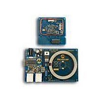
KIT ACC TIRE PRESSURE MON SYSTEM
Manufacturer
Microchip Technology
Type
Automotive, Tire Pressure Monitorr
Datasheet
1.APGAC031.pdf
(12 pages)
Specifications of APGAC031
Frequency
315MHz
Processor To Be Evaluated
PIC18F2680
Lead Free Status / RoHS Status
Lead free / RoHS Compliant
For Use With/related Products
APGRD003
Lead Free Status / Rohs Status
Lead free / RoHS Compliant


AN238
Sensonor SP-13 Sensor IC
The SP-13 sensor IC performs several functions. It
measures pressure, temperature, and generates a flag
when the battery voltage drops below a predetermined
threshold. The SP-13 has five unique modes:
1.
2.
3.
4.
5.
The SP-13 also includes a 32-bit identification number
that is programmed into the device at the time of
manufacture. This unique ID, when used by the central
receiver, allows differentiation between S/TXs.
Sensonor, as well as several other manufacturers,
continue to offer enhanced pressure sensing devices of
varying functionality. Therefore, it is recommended that
a TPM developer thoroughly research the market prior
to making a final pressure sensor selection.
DS00238C-page 4
Storage mode: If the pressure is below 1.5 bar,
pressure is measured every 60 seconds but no
data is sent. If the pressure increases above
1.5 bars, the component shifts into the Initial
mode.
Initial mode: This mode occurs at power on or
if the pressure increases above 1.5 bar from
Storage mode. In this mode, pressure is
measured every 0.85 seconds and data is sent
every 0.85 seconds. This sequence is repeated
256 times. After the sequence is repeated 256
times, the device shifts into the Normal mode
only if pressure is above 1.5 bar. If the pressure
is below 1.5 bar, the device will shift into the
Storage mode.
Normal mode: Pressure is measured every
3.4 seconds and data is transmitted every
60 seconds. If the measured pressure differs by
more than 200 mbar from the reference taken
every 60 seconds, the device enters a Pressure
Alert mode.
Pressure Alert mode: It is the same measure-
ment and transmitting pattern as the Initial
mode.
High Temp Alert mode: If the temperature
exceeds 120°C, the SP-13 device enters into
the same measurement and transmitting pattern
as the Initial mode.
FIGURE 3:
LF Input Circuitry
The LF input is designed to receive and demodulate a
125 kHz signal and transform the received data into a
specific command. The LF input circuit makes use of
the internal comparator of the rfPIC microcontroller,
thereby reducing cost, module size and quiescent cur-
rent. The LF input circuitry features a LC tank circuit
that is tuned to 125 kHz. The LF sensing input com-
prises L1 and C11. L1 is specially designed by Coilcraft
for this type of application. It provides good sensitivity
in a compact package. A conventional coil could be
used in its place, but overall circuit sensitivity or range
would be reduced. Schottky diode D3 is used to clamp
the voltage developed across the LC tank to safe lev-
els. The output of the LC tank circuit, after passing
through current limiting resistor R5, is fed into the rfPIC
microcontroller comparator’s negative input. The com-
parator’s positive input is configured as V
the rfPIC12F675 V
parator is then fed into an envelope detector consisting
of Schottky diode D2, capacitor C9 and resistor R3. C9
and R3 are selected to provide adequate filtering of the
LF frequency without rounding the edges of the desired
data signal. The output of the envelope detector is then
fed directly into a port pin on the rfPIC microcontroller
and used to process the LF data.
Without a limiting diode, the LF input circuit may be
prone to being overdriven when strong LF fields are
present. This can be seen when the LF commander
device is in close proximity to the S/TX device. The
envelope detection circuit can be abandoned to reduce
cost, but doing so would require additional data
extraction software.
5.6 MΩ
R4
Pressure/Temperature Sensor IC
1
2
3
4
5
6
7
GND1
GND2
GND3
V
R
GND4
V
SP-13_SO
SS
EXT
SS
REF
SENSONOR SP-13 SENSOR
IC
U4
module. The output of the com-
GND5
TXON
TXBC
© 2009 Microchip Technology Inc.
AV
TXD
V
V
DD
DD
SS
14
13
12
11
10
9
8
x
x
+3V
0.01 μF
C10
REF
through
GP0
Related parts for APGAC031
Image
Part Number
Description
Manufacturer
Datasheet
Request
R

Part Number:
Description:
Manufacturer:
Microchip Technology Inc.
Datasheet:
Part Number:
Description:
Manufacturer:
Microchip Technology Inc.
Datasheet:
Part Number:
Description:
Manufacturer:
Microchip Technology Inc.
Datasheet:
Part Number:
Description:
Manufacturer:
Microchip Technology Inc.
Datasheet:
Part Number:
Description:
Manufacturer:
Microchip Technology Inc.
Datasheet:
Part Number:
Description:
Manufacturer:
Microchip Technology Inc.
Datasheet:
Part Number:
Description:
Manufacturer:
Microchip Technology Inc.
Datasheet:
Part Number:
Description:
Manufacturer:
Microchip Technology Inc.
Datasheet: