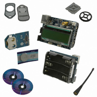
4010-DAAKF_434 Silicon Laboratories Inc, 4010-DAAKF_434 Datasheet - Page 9

4010-DAAKF_434
Manufacturer Part Number
4010-DAAKF_434
Description
KIT DEV KEYFOB 434MHZ FOR SI4010
Manufacturer
Silicon Laboratories Inc
Series
EZRadio®r
Type
Key Fobr
Datasheets
1.4010-DAAKF_434.pdf
(2 pages)
2.4010-DAAKF_434.pdf
(14 pages)
3.4010-DKKF_434.pdf
(16 pages)
Specifications of 4010-DAAKF_434
Frequency
434MHz
Wireless Frequency
27 MHz to 960 MHz
Modulation
FSK, OOK
Output Power
10 dBm
Antenna
SMA
For Use With/related Products
Si4010
Lead Free Status / RoHS Status
Lead free / RoHS Compliant
Lead Free Status / RoHS Status
Lead free / RoHS Compliant, Lead free / RoHS Compliant
Other names
336-1981
device, since for that program level the C2 interface is turned off after the boot-by-boot routine.
However, when the code above is used for a device in the Factory or User programming state, then the GPIO4 will
stop working after the first LED blink. The LED must be seen to be turned on and off by the application (to blink) to
experience this problem.
2.8.2. Solution 1: Living with the Limitation
The simplest solution is to know about the issue and decide to live with it. After the first LED blink, the GPI04 will
not work. In this scenario, the user may decide to test the GPI04 only when the part is fully programmed as the Run
part.
2.8.3. Solution 2: Controlled Compilation
The user may use a #define C statement to define a LED "on" value. For button press debugging purposes when
the LED can be off the code is compiled with value set as 0, so the LED will never light up and the GPIO4 will
always function. For debugging the LED, and for final application compilation for the Run state of the device, the
user will compile the application with the LED "on" value set to 1.
For example:
#ifdef DEBUG
#else
#endif
/* Clear the GPIO_LED off after reset .. reset will set this bit! */
GPIO_LED = 0;
/* Set LED intensity .. acceptable values are 0 (off) or 1, 2, and 3 */
vSys_LedIntensity( 3 );
/* Turn the LED on at currently set intensity */
GPIO_LED = gLedOnValue_c;
/* Turn the LED off, keep the intensity setting */
GPIO_LED = 0;
One advantage of this solution is that the code size is identical in both cases, Debug or Run. Cycling the power to
the part in this context means either physical removal of the power to the device or calling the vSys_Shutdown()
function from within the application, which achieves the same result.
2.8.4. Solution 3: Dynamic C2 Disable (Recommended)
The GPI04 issue manifests itself when the LED is actually being turned on and off from the application. The LED
physically blinks and is not blocked from being lit up by an application being connected to the IDE debug chain, and
the C2 interface is active and enabled.
If we disable the C2 interface when the device is not connected to the IDE chain, and before the LED is turned off
when lit, then there will not be the GPIO4 problem. To do that the user must add the following function to the user
application to turn the LED on.
#define gLedOnValue_c
#define gLedOnValue_c
…
…
0
1
Rev. 0.1
Si4010-Key Fob-DK
9


