4010-DAAKF_434 Silicon Laboratories Inc, 4010-DAAKF_434 Datasheet - Page 8
4010-DAAKF_434
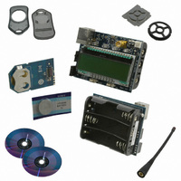
Manufacturer Part Number
4010-DAAKF_434
Description
KIT DEV KEYFOB 434MHZ FOR SI4010
Manufacturer
Silicon Laboratories Inc
Series
EZRadio®r
Type
Key Fobr
Datasheets
1.4010-DAAKF_434.pdf
(2 pages)
2.4010-DAAKF_434.pdf
(14 pages)
3.4010-DKKF_434.pdf
(16 pages)
Specifications of 4010-DAAKF_434
Frequency
434MHz
Wireless Frequency
27 MHz to 960 MHz
Modulation
FSK, OOK
Output Power
10 dBm
Antenna
SMA
For Use With/related Products
Si4010
Lead Free Status / RoHS Status
Lead free / RoHS Compliant
Lead Free Status / RoHS Status
Lead free / RoHS Compliant, Lead free / RoHS Compliant
Other names
336-1981


Si4010-Key Fob-DK
2.8. Hardware Issue with Debugging LED Application
There is an issue with the LED turning on and off and the functionality of the GPI04. There is no issue when the
part is programmed as the Run part and runs the final application code. Therefore, the issue affects only the
application development. There are several possible software workarounds, depending on the approach the user
wants to take.
2.8.1. Application LED Control
The user can control the LED intensity and whether the LED is on or off. The LED intensity has 4 values, 0 to 3:
Off, 0.3 mA, 0.6 mA, and 1 mA current. The user can set the intensity any time, but the LED is not going to be
turned on until the GPIO_LED is set to 1. The GPIO_LED is an alias for the P0.5 bit.
After the reset the P0.5 bit is set to 1, so it is recommended that the user use GPIO_LED = 0 at the beginning of the
user application.
To turn the LED off at the very beginning of the user application:
/* Clear the GPIO_LED.. reset will set this bit! */
GPIO_LED = 0;
To turn the LED on and off inside the user application:
/* Set LED intensity .. acceptable values are 0 (off) or 1, 2, and 3 */
vSys_LedIntensity( 3 );
/* To turn the LED on at currently set intensity */
GPIO_LED = 1;
/* To turn the LED off, keep the intensity setting */
GPIO_LED = 0;
The intensity setting can be changed any time, even when the GPIO_LED = 1.
This is basically how the LED control operates. This approach will work when the part status is finalized as the Run
8
3. Once the IDE chain is disconnected from the device (for example, by pressing the Disconnect button in
4. If the user wants to reconnect the IDE to the device the only requirement is that the LED must not be lit by
can be written in a normal fashion using LED as desired in the final application without worry of being dis-
connected from the debug chain. The only limitation is that the LED will not be lit from the application dur-
ing the IDE debug session. The user will still observe LED activity, but that activity is related to the debug
chain communicating with the device, not the user application driving the LED.
the IDE), the device is released from halt and at the same time the blocking of the LED driver is removed.
From that point on, the application behaves and runs as a regular application and the LED activity reflects
what the application desires to do with the LED.
the application and the C2 debug interface must be active, not being actively turned off by the application.
Therefore, if the device user software is stuck in an infinite loop and driving the LED constantly or the C2
interface was turned off by the application, the IDE chain will not be able to connect to the device. In such
a situation, the device power has to be cycled to invoke internal power on reset. (See item 1 above.)
Cycling the power to the part in this context means either physical removal of the power to the device or
calling the vSys_Shutdown() function from within the application, which achieves the same result.
…
…
Rev. 0.1
Related parts for 4010-DAAKF_434
Image
Part Number
Description
Manufacturer
Datasheet
Request
R

Part Number:
Description:
SMD/C°/SINGLE-ENDED OUTPUT SILICON OSCILLATOR
Manufacturer:
Silicon Laboratories Inc
Part Number:
Description:
Manufacturer:
Silicon Laboratories Inc
Datasheet:
Part Number:
Description:
N/A N/A/SI4010 AES KEYFOB DEMO WITH LCD RX
Manufacturer:
Silicon Laboratories Inc
Datasheet:
Part Number:
Description:
N/A N/A/SI4010 SIMPLIFIED KEY FOB DEMO WITH LED RX
Manufacturer:
Silicon Laboratories Inc
Datasheet:
Part Number:
Description:
N/A/-40 TO 85 OC/EZLINK MODULE; F930/4432 HIGH BAND (REV E/B1)
Manufacturer:
Silicon Laboratories Inc
Part Number:
Description:
EZLink Module; F930/4432 Low Band (rev e/B1)
Manufacturer:
Silicon Laboratories Inc
Part Number:
Description:
I°/4460 10 DBM RADIO TEST CARD 434 MHZ
Manufacturer:
Silicon Laboratories Inc
Part Number:
Description:
I°/4461 14 DBM RADIO TEST CARD 868 MHZ
Manufacturer:
Silicon Laboratories Inc
Part Number:
Description:
I°/4463 20 DBM RFSWITCH RADIO TEST CARD 460 MHZ
Manufacturer:
Silicon Laboratories Inc
Part Number:
Description:
I°/4463 20 DBM RADIO TEST CARD 868 MHZ
Manufacturer:
Silicon Laboratories Inc
Part Number:
Description:
I°/4463 27 DBM RADIO TEST CARD 868 MHZ
Manufacturer:
Silicon Laboratories Inc
Part Number:
Description:
I°/4463 SKYWORKS 30 DBM RADIO TEST CARD 915 MHZ
Manufacturer:
Silicon Laboratories Inc
Part Number:
Description:
N/A N/A/-40 TO 85 OC/4463 RFMD 30 DBM RADIO TEST CARD 915 MHZ
Manufacturer:
Silicon Laboratories Inc
Part Number:
Description:
I°/4463 20 DBM RADIO TEST CARD 169 MHZ
Manufacturer:
Silicon Laboratories Inc