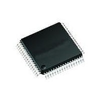
71M6511H-IGT/F Maxim Integrated Products, 71M6511H-IGT/F Datasheet - Page 37

71M6511H-IGT/F
Manufacturer Part Number
71M6511H-IGT/F
Description
IC ENERGY METER RESIDENT 64-LQFP
Manufacturer
Maxim Integrated Products
Datasheet
1.71M6511H-IGTF.pdf
(98 pages)
Specifications of 71M6511H-IGT/F
Processor Series
6511x
Core
80515
Data Bus Width
8 bit
Program Memory Type
Flash
Program Memory Size
64 KB
Data Ram Size
7 KB
Interface Type
I2C, SSI, UART
Maximum Clock Frequency
5 MHz
Number Of Programmable I/os
12
Number Of Timers
2
Operating Supply Voltage
3 V to 3.6 V
Maximum Operating Temperature
+ 85 C
Mounting Style
SMD/SMT
Package / Case
LQFP-64
3rd Party Development Tools
PK51, CA51, A51, ULINK2
Development Tools By Supplier
71M6511H-DB
Minimum Operating Temperature
- 40 C
On-chip Adc
22 bit Delta Sigma
Lead Free Status / RoHS Status
Lead free / RoHS Compliant
Available stocks
Company
Part Number
Manufacturer
Quantity
Price
Company:
Part Number:
71M6511H-IGT/F
Manufacturer:
PERICOM
Quantity:
1 200
Company:
Part Number:
71M6511H-IGT/F
Manufacturer:
Maxim Integrated
Quantity:
10 000
On-Chip Resources
DIO Ports
The 71M6511/6511H includes up to 12 pins of general purpose digital I/O. These pins are dual function and can alternatively
be used as LCD drivers. Figure 8 shows a block diagram of the DIO section.
On reset or power-up, all DIO pins are inputs until they are configured for the desired direction. The pins are configured and
controlled by the DIO and DIO_DIR registers (SFRs) and by the five bits of the I/O register LCD_NUM (0x2020[4:0]). See the
description for LCD_NUM in the I/O RAM Section for a table listing the available segment pins versus DIO pins, depending on
the selection for LCD_NUM. Generally, increasing the value for LCD_NUM will configure an increasing number of general
purpose pins to be LCD segment pins, starting at the higher pin numbers.
Each pin declared as DIO can be configured independently as an input or output with the bits of the DIO_DIRn registers. Table
52 lists the direction registers and configurability associated with each group of DIO pins. Table 53 shows the configuration for
a DIO pin through its associated bit in its DIO_DIR register.
DIO
Pin number
Data Register bit
Direction Register
bit
Internal Resources
Configurable
Page: 37 of 98
DIO
Pin number
Data Register bit
Direction Register
bit
Internal Resources
Configurable
A Maxim Integrated Products Brand
Table 52: Data/Direction Registers and Internal Resources for DIO Pin Groups
16
22
N
0
0
17
12
N
1
1
--
--
--
--
0
DIO_DIR2 (SFR 0xA1)
DIO2=P2 (SFR 0xA0)
18
--
--
--
--
--
--
--
--
1
© 2005–2010 Teridian Semiconductor Corporation
DIO_DIR0 (SFR 0xA2)
19
DIO0=P0 (SFR 0x80)
--
--
--
--
2
--
--
--
--
Figure 8: DIO Ports Block Diagram
LCD_NUM
LCD_MODE
LCD_CLK
LCD_EN
DIO_EEX
PULSEV/W
DIO_IN
DIO_OUT
LCD_NUM
DIO_GP
20
--
--
--
--
LCD DISPLAY
DIGITAL I/O
3
--
--
--
--
DRIVER
21
--
--
--
--
37
Y
4
4
4
22
--
--
--
--
38
Y
5
5
5
23
--
--
--
--
39
Y
6
6
6
Single-Phase Energy Meter IC
COM0..3
SEG0..SEG2
SEG8..SEG19
SEG24/DIO4 ...
SEG31/DIO11
SEG34/DIO14 ...
SEG37/DIO17
40
SEG3/SCLK
SEG4/SSDATA
SEG5/SFR
SEG6/SRDY
SEG7/
MUX_SYNC
Y
7
7
7
41
8
0
0
Y
71M6511/71M6511H
42
Y
9
1
1
DATA SHEET
DIO_DIR1 (SFR 0x91)
DIO1=P1 (SFR 0x90)
10
43
Y
2
2
11
44
Y
3
3
12
--
--
--
--
13
--
--
--
--
NOVEMBER 2010
14
20
N
6
6
15
21
N
7
7
V2.7


