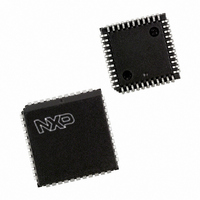
P89C662HBA/00,512 NXP Semiconductors, P89C662HBA/00,512 Datasheet - Page 64

P89C662HBA/00,512
Manufacturer Part Number
P89C662HBA/00,512
Description
IC 80C51 MCU FLASH 32K 44-PLCC
Manufacturer
NXP Semiconductors
Series
89Cr
Datasheet
1.P89C660HBA00512.pdf
(89 pages)
Specifications of P89C662HBA/00,512
Core Processor
8051
Core Size
8-Bit
Speed
33MHz
Connectivity
I²C, UART/USART
Peripherals
POR, PWM, WDT
Number Of I /o
32
Program Memory Size
32KB (32K x 8)
Program Memory Type
FLASH
Ram Size
1K x 8
Voltage - Supply (vcc/vdd)
4.5 V ~ 5.5 V
Oscillator Type
Internal
Operating Temperature
0°C ~ 70°C
Package / Case
44-PLCC
Lead Free Status / RoHS Status
Lead free / RoHS Compliant
Eeprom Size
-
Data Converters
-
Other names
568-1269-5
935267444512
P89C662HBA
935267444512
P89C662HBA
Available stocks
Company
Part Number
Manufacturer
Quantity
Price
Company:
Part Number:
P89C662HBA/00,512
Manufacturer:
NXP Semiconductors
Quantity:
10 000
Philips Semiconductors
Power-On Reset Code Execution
The P89C660/662/664/668 contains two special Flash registers: the
BOOT VECTOR and the STATUS BYTE. At the falling edge of reset,
the P89C660/662/664/668 examines the contents of the Status
Byte. If the Status Byte is set to zero, power-up execution starts at
location 0000H, which is the normal start address of the user’s
application code. When the Status Byte is set to a value other than
zero, the contents of the Boot Vector is used as the high byte of the
execution address and the low byte is set to 00H. The factory
default setting is 0FCH, corresponds to the address 0FC00H for the
factory masked-ROM ISP boot loader. A custom boot loader can be
written with the Boot Vector set to the custom boot loader.
2002 Oct 28
80C51 8-bit Flash microcontroller family
16KB/32KB/64KB ISP/IAP Flash with 512B/1KB/2KB/8KB RAM
NOTE: When erasing the Status Byte or Boot Vector,
both bytes are erased at the same time. It is necessary
to reprogram the Boot Vector after erasing and
updating the Status Byte.
89C664/89C668
89C662
89C660
PROGRAM
ADDRESS
Figure 55. Flash Memory Configurations
FFFF
C000
8000
4000
2000
0000
64
16 KBYTES
16 KBYTES
16 KBYTES
8 KBYTES
8 KBYTES
BLOCK 4
BLOCK 3
BLOCK 2
BLOCK 1
BLOCK 0
If the factory default setting for the Boot Vector (0FCH) is changed, it
After programming the Flash, the status byte should be programmed
Hardware Activation of the Boot Loader
The boot loader can also be executed by holding PSEN LOW, P2.7,
P2.6 high, EA greater than V
not connected) at the falling edge of RESET. This is the same effect
as having a non-zero status byte. This allows an application to be
built that will normally execute the end user’s code but can be
manually forced into ISP operation.
will no longer point to the ISP masked-ROM boot loader code. If this
happens, the only possible way to change the contents of the Boot
Vector is through the parallel programming method, provided that
the end user application does not contain a customized loader that
provides for erasing and reprogramming of the Boot Vector and
Status Byte.
to zero in order to allow execution of the user’s application code
beginning at address 0000H.
P89C660/P89C662/P89C664/
BOOT ROM
(1 KBYTE)
IH
(such as +5 V), and ALE HIGH (or
FFFF
FC00
SU01264
P89C668
Product data


