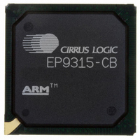
EP9315-CB Cirrus Logic Inc, EP9315-CB Datasheet - Page 208

EP9315-CB
Manufacturer Part Number
EP9315-CB
Description
IC ARM920T MCU 200MHZ 352-PBGA
Manufacturer
Cirrus Logic Inc
Series
EP9r
Specifications of EP9315-CB
Core Processor
ARM9
Core Size
16/32-Bit
Speed
200MHz
Connectivity
EBI/EMI, EIDE, Ethernet, I²C, IrDA, Keypad/Touchscreen, PCMCIA, SPI, UART/USART, USB
Peripherals
AC'97, DMA, I²:S, LCD, LED, MaverickKey, POR, PWM, WDT
Number Of I /o
16
Program Memory Type
ROMless
Ram Size
32K x 8
Voltage - Supply (vcc/vdd)
1.65 V ~ 3.6 V
Data Converters
A/D 8x12b
Oscillator Type
External
Operating Temperature
0°C ~ 70°C
Package / Case
352-BGA
Processor Series
EP93xx
Core
ARM920T
Data Bus Width
32 bit
3rd Party Development Tools
MDK-ARM, RL-ARM, ULINK2
Development Tools By Supplier
EDB9315A-Z
For Use With
598-1144 - KIT DEVELOPMENT EP9315 ARM9
Lead Free Status / RoHS Status
Contains lead / RoHS non-compliant
Eeprom Size
-
Program Memory Size
-
Lead Free Status / Rohs Status
No
Other names
598-1261
Available stocks
Company
Part Number
Manufacturer
Quantity
Price
Part Number:
EP9315-CBZ
Manufacturer:
CIRRUS
Quantity:
20 000
- Current page: 208 of 824
- Download datasheet (13Mb)
7
7-26
7.4.9.1.1
7.4.9.1.2
7.4.9.1.3
Raster Engine With Analog/LCD Integrated Timing and Interface
EP93xx User’s Guide
7.4.9.1 Registers Used for Cursor
The X location value controls the starting horizontal X location of the cursor image. The value
is compared to the horizontal pixel counter and should be set by software to be between the
active start and active stop horizontal pixel values. The cursor hardware will clip the cursor at
the right edge of the screen. This value is also used to control the starting location for the
cursor image on the upper half of the screen during dual scan mode. To prevent cursor
distortion, the new X location value will not be used until the next frame.
During dual scan display mode, selected by writing DSCAN = ‘1’ to the
the lower half Y value controls the starting vertical Y location on the lower half of the screen
for the cursor image. The value is compared to the vertical line counter and should be set by
software to be between the active start and active stop vertical line values. The cursor
hardware will clip the cursor at the bottom of the screen. To prevent cursor distortion, the new
location value will not be used until the next frame.
The hardware cursor circuitry has a separate blinking function. The rate is a 50% duty cycle
programmable number of vertical frame intervals. When a blink frame is active, the color
RGB mux switches in 24-bit
“CursorColor1,”
The registers used for configuring the Hardware Cursor are:
“CursorAdrReset”
CursorDScanLHYLoc. The following subsections describe the function of each of these
registers.
This register contains the memory starting address for the cursor image.
This register contains the address for the part of the cursor that is displayed next after
reaching the last line of the cursor. This register is needed to support DUAL scan displays.
For non-dual scan displays, this address is the same as that in the CursorAdrStart register.
This register selects four parameters that will impact the cursor size: CSTEP, CLINS, CWID,
and DLNS.
Two bits select the cursor step size:
0 0
0 1
1 0
1 1
CursorAdrStart Register
CursorAdrReset Register
CursorSize Register
Step by 1 word or 16 pixels
Step by 2 words or 32 pixels
Step by 3 words or 48 pixels
Step by 4 words or 64 pixels
or
CSTEP
,
“CursorColor2,”
“CursorSize”
“CursorBlinkColor1,”
Copyright 2007 Cirrus Logic
,
“CursorColor1,” “CursorColor2,”
respectively.
or
“CursorBlinkColor2”
“CursorAdrStart”
,
“CursorXYLoc”
“PixelMode”
values for
,
DS785UM1
register,
and
Related parts for EP9315-CB
Image
Part Number
Description
Manufacturer
Datasheet
Request
R

Part Number:
Description:
IC ARM9 SOC ENH UNIV 352PBGA
Manufacturer:
Cirrus Logic Inc
Datasheet:

Part Number:
Description:
32-Bit Microcontroller IC
Manufacturer:
Cirrus Logic Inc
Datasheet:

Part Number:
Description:
IC ARM920T MCU 200MHZ 352-PBGA
Manufacturer:
Cirrus Logic Inc
Datasheet:

Part Number:
Description:
MCU, MPU & DSP Development Tools Eval Bd Uni. ARM9 SOC Processor
Manufacturer:
Cirrus Logic Inc
Datasheet:

Part Number:
Description:
IC ARM920T MCU 166MHZ 208-LQFP
Manufacturer:
Cirrus Logic Inc
Datasheet:

Part Number:
Description:
IC ARM920T MCU 200MHZ 352-PBGA
Manufacturer:
Cirrus Logic Inc
Datasheet:

Part Number:
Description:
IC ARM920T MCU 166MHZ 208-LQFP
Manufacturer:
Cirrus Logic Inc
Datasheet:

Part Number:
Description:
Development Kit
Manufacturer:
Cirrus Logic Inc
Datasheet:

Part Number:
Description:
Development Kit
Manufacturer:
Cirrus Logic Inc
Datasheet:

Part Number:
Description:
High-efficiency PFC + Fluorescent Lamp Driver Reference Design
Manufacturer:
Cirrus Logic Inc
Datasheet:

Part Number:
Description:
Development Kit
Manufacturer:
Cirrus Logic Inc
Datasheet:

Part Number:
Description:
Development Kit
Manufacturer:
Cirrus Logic Inc
Datasheet:

Part Number:
Description:
Development Kit
Manufacturer:
Cirrus Logic Inc
Datasheet:

Part Number:
Description:
Ref Bd For Speakerbar MSA & DSP Products
Manufacturer:
Cirrus Logic Inc


