IRL3502 International Rectifier, IRL3502 Datasheet
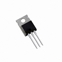
MOSFET N-CH 20V 110A TO-220AB

IRL3502

Manufacturer Part Number
IRL3502
Description
MOSFET N-CH 20V 110A TO-220AB
Manufacturer
International Rectifier
Series
HEXFET®r
Datasheet

Specifications of IRL3502

Fet Type
MOSFET N-Channel, Metal Oxide
Fet Feature
Logic Level Gate
Rds On (max) @ Id, Vgs
7 mOhm @ 64A, 7V
Drain To Source Voltage (vdss)
20V
Current - Continuous Drain (id) @ 25° C
110A
Vgs(th) (max) @ Id
700mV @ 250µA
Gate Charge (qg) @ Vgs
110nC @ 4.5V
Input Capacitance (ciss) @ Vds
4700pF @ 15V
Power - Max
140W
Mounting Type
Through Hole
Package / Case
TO-220-3 (Straight Leads)
Lead Free Status / RoHS Status
Contains lead / RoHS non-compliant
Other names
*IRL3502

Available stocks

Company
Part Number
Manufacturer
Quantity
Price
Part Number:
IRL3502
Manufacturer:
IR
Quantity:
12 500
Part Number:
IRL3502PBF
Manufacturer:
International Rectifier
Quantity:
135
Part Number:
IRL3502S
Manufacturer:
IR
Quantity:
20 000
Part Number:
IRL3502STRPBF
Manufacturer:
IR
Quantity:
20 000
Description
These HEXFET Power MOSFETs were designed
specifically to meet the demands of CPU core DC-DC
converters.
combined with an optimized gate oxide design results
in a die sized specifically to offer maximum efficiency
at minimum cost.
The TO-220 package is universally preferred for all
commercial-industrial applications at power dissipation
levels to approximately 50 watts. The low thermal
resistance and low package cost of the TO-220
contribute to its wide acceptance throughout the
industry.
Absolute Maximum Ratings
Thermal Resistance
I
I
I
P
V
V
E
I
E
dv/dt
T
T
R
R
R
D
D
DM
AR
J
STG
D
GS
GSM
AS
AR
@ T
@ T
JC
CS
JA
Advanced Process Technology
Optimized for 4.5V-7.0V Gate Drive
Ideal for CPU Core DC-DC Converters
Fast Switching
@T
C
C
C
= 25°C
= 100°C
= 25°C
Advanced processing techniques
Power Dissipation
Peak Diode Recovery dv/dt
Continuous Drain Current, V
Pulsed Drain Current
Linear Derating Factor
Gate-to-Source Voltage
(Start Up Transient, tp = 100µs)
Single Pulse Avalanche Energy
Avalanche Current
Repetitive Avalanche Energy
Operating Junction and
Storage Temperature Range
Soldering Temperature, for 10 seconds
Mounting torque, 6-32 or M3 srew
Junction-to-Case
Case-to-Sink, Flat, Greased Surface
Junction-to-Ambient
Parameter
Parameter
PRELIMINARY
GS
GS
@ 5.0V
@ 5.0V
G
Typ.
300 (1.6mm from case )
0.50
–––
–––
HEXFET
10 lbf•in (1.1N•m)
-55 to + 150
S
D
110
Max.
TO-220AB
420
140
± 10
390
1.1
5.0
67
64
14
14
®
R
IRL3502
Power MOSFET
DS(on)
Max.
I
V
0.89
–––
D
62
DSS
= 110A
= 0.007
PD 9.1698A
= 20V
Units
Units
W/°C
°C/W
V/ns
mJ
mJ
°C
W
V
A
V
A
11/17/97

Related parts for IRL3502

IRL3502 Summary of contents

Page 1

... Case-to-Sink, Flat, Greased Surface CS R Junction-to-Ambient JA PRELIMINARY HEXFET 5. 5. 150 300 (1.6mm from case ) 10 lbf•in (1.1N•m) Typ. ––– 0.50 ––– PD 9.1698A IRL3502 ® Power MOSFET V = 20V DSS R = 0.007 DS(on 110A D TO-220AB Max. Units 110 67 A 420 140 W 1.1 W/° ...

Page 2

... IRL3502 Electrical Characteristics @ T Parameter V Drain-to-Source Breakdown Voltage (BR)DSS Breakdown Voltage Temp. Coefficient (BR)DSS J R Static Drain-to-Source On-Resistance DS(on) V Gate Threshold Voltage GS(th) g Forward Transconductance fs I Drain-to-Source Leakage Current DSS Gate-to-Source Forward Leakage I GSS Gate-to-Source Reverse Leakage Q Total Gate Charge g Q Gate-to-Source Charge ...

Page 3

... BOTTOM 2.25V 100 2.25V 10 0 Drain-to-Source Voltage (V) DS Fig 2. Typical Output Characteristics 2.0 110A 1.5 1.0 0.5 0.0 -60 -40 - Junction Temperature Fig 4. Normalized On-Resistance Vs. Temperature IRL3502 20µs PULSE WIDTH ° 150 100 100 120 140 160 ° ...

Page 4

... IRL3502 8000 iss rss oss ds 6000 C iss 4000 C oss 2000 C rss Drain-to-Source Voltage (V) DS Fig 5. Typical Capacitance Vs. Drain-to-Source Voltage 1000 ° 150 C J 100 ° 0.5 1.0 1.5 V ,Source-to-Drain Voltage (V) SD Fig 7. Typical Source-Drain Diode Forward Voltage f = 1MHz C SHORTED 100 ...

Page 5

... Fig 11. Maximum Effective Transient Thermal Impedance, Junction-to-Case 800 600 400 200 0 125 150 25 ° Starting T , Junction Temperature( C) Fig 10. Maximum Avalanche Energy 0.001 0. Rectangular Pulse Duration (sec) 1 IRL3502 TOP BOTTOM 50 75 100 125 J Vs. Drain Current Notes: 1. Duty factor ...

Page 6

... IRL3502 0.014 0.012 0.010 0.008 0.006 0.004 rain C urrent (A) D Fig 12. On-Resistance Vs. Drain Current Fig 13. On-Resistance Vs. Gate Voltage 0.010 0.008 I = 64A D 0.006 0.004 2.0 3.0 4.0 5 Gate-to-Source Voltage ( 6.0 7.0 8.0 ...

Page 7

... TIF GERMANY: Saalburgstrasse 157, 61350 Bad Homburg Tel 6172 96590 IR ITALY: Via Liguria 49, 10071 Borgaro, Torino Tel 451 0111 Data and specifications subject to change without notice. IRL3502 - B - 4.69 (.185 ) 4.20 (.165 ) 1.32 (.052) 1.22 (.048 0.55 (.022) 3X 0.46 (.018) 2.92 (.115) 2 ...

Page 8

Note: For the most current drawings please refer to the IR website at: http://www.irf.com/package/ ...

Related keywords