ST203C107MAJ05 AVX Corporation, ST203C107MAJ05 Datasheet - Page 99
ST203C107MAJ05
Manufacturer Part Number
ST203C107MAJ05
Description
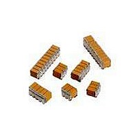
CAP CER 100UF 25V STACKED SMD
Manufacturer
AVX Corporation
Series
TurboCap™r
Specifications of ST203C107MAJ05
Capacitance
100µF
Tolerance
±20%
Temperature Coefficient
X7R
Voltage - Rated
25V
Mounting Type
Surface Mount, MLCC
Operating Temperature
-55°C ~ 125°C
Features
Stacked
Applications
Filtering Switch Mode Power Supplies
Package / Case
10-Stacked SMD, J-Lead
Size / Dimension
0.525" L x 0.300" W (13.34mm x 7.62mm)
Thickness
5.59mm Max
Lead Style
J-Lead
Voltage Rating
25 Volts
Operating Temperature Range
- 55 C to + 125 C
Product
General Type MLCCs
Dielectric Characteristic
X7R
Capacitance Tolerance
± 20%
Capacitor Case Style
DIP
No. Of Pins
10
Capacitor Mounting
SMD
Rohs Compliant
No
Termination Style
Radial
Lead Spacing
6.35 mm
Dimensions
7.62 mm W x 13.34 mm L x 5.59 mm H
Dissipation Factor Df
2.5
Lead Free Status / RoHS Status
Contains lead / RoHS non-compliant
Ratings
-
Lead Spacing
-
Lead Free Status / RoHS Status
Contains lead / RoHS non-compliant
Other names
478-6116


High Voltage MLC Leaded Chips
For 600V to 5000V Applications
HOW TO ORDER
Note: Capacitors with X7R dielectrics are not intended for applications across AC supply mains or AC line filtering with polarity reversal. Contact plant for recommendations.
DIMENSIONS
Note: For W (Epoxy Coated) part add 0.127 (0.005) to max. and nominal dimensions A, B, D, & E
98
1825
Style
1825
2225
3640
AVX
Capacitors may require protective surface coating to prevent external arcing.
Style
1825
2225
3640
(0.250) MIN.
600V/630V = C
6.35
B
B
B
Voltage
1000V = A
1500V = S
2000V = G
2500V = W
3000V = H
4000V = J
5000V = K
A
A
A
A
2.54 (0.100)
D
A (max.)
D
D
2.54 (0.100) MAX.
2.54 (0.100) MAX.
2.54 (0.100) MAX.
0.635 (0.025) MIN.
0.635 (0.025) MIN.
0.635 (0.025) MIN.
2.54 (0.100) TY P .
2.54 (0.100) TYP.
2.54 (0.100) TYP.
Temperature
Coefficient
C0G = A
X7R = C
1.397 (0.055)
±0.254 (0.010)
1.397 (0.055)
±0.254 (0.010)
1.397 (0.055)
±0.254 (0.010)
0.508 (0.020) TY P .
0.508 (0.020) TYP.
0.508 (0.020) TYP.
A
Dimension = 4.58 (0.180)
Dimension = 4.19 (0.165)
For “N” Style Leads, “B”
For “J” & “L” Leads, “B”
Capacitance Code
Examples:
220,000 pF = 224
(2 significant digits
B (max.)
22,000 pF = 223
+ no. of zeros)
1,000 pF = 102
100 pF = 101
10 pF = 100
271
“N” STYLE
“L” STYLE
“J” STYLE
LEADS
LEADS
LEADS
C0G:J = ±5%
X7R:K = ±10%
C ±.635 (±0.025)
Capacitance
Tolerance
5.08 (0.200)
6.35 (0.250)
10.2 (0.400)
M = ±20%
M = ±20%
K = ±10%
Z = +80%,
K
-20%
A = Standard
0.254 (0.010) RAD. (TY P . )
Test Level
0.254 (0.010) RAD. (TYP.)
1.778 (0.070)
±
D ±.635 (±0.025)
±
0.254 (0.010)
A
1.778 (0.070)
0.254 (0.010)
6.35 (0.250)
6.35 (0.250)
10.2 (0.400)
W = Epoxy Coated
V = Uncoated
Finish
V
6.86 (0.270)
7.62 (0.300)
11.2 (0.440)
C
E
C
E
E
C
E (max.)
00N = Straight Lead
00L = Leads Formed Out
00J = Leads Formed In
1.905 (0.075)
±
TYP.
0.254 (0.010) TYP.
0.254 (0.010) TYP.
0.635 (0.025)
1.905 (0.075)
±
TY P .
0.254 (0.010) TY P .
millimeters (inches)
0.635 (0.025)
Lead Style
00N
No. of Leads
per side
3
3
4
Related parts for ST203C107MAJ05
Image
Part Number
Description
Manufacturer
Datasheet
Request
R

Part Number:
Description:
Inverter Grade Thyristors
Manufacturer:
International Rectifier Corp.
Datasheet:

Part Number:
Description:
Manufacturer:
AVX Corporation
Datasheet:
Part Number:
Description:
Manufacturer:
AVX Corporation
Datasheet:
Part Number:
Description:
Manufacturer:
AVX Corporation
Datasheet:
Part Number:
Description:
Manufacturer:
AVX Corporation
Datasheet: