ST203C107MAJ05 AVX Corporation, ST203C107MAJ05 Datasheet - Page 87
ST203C107MAJ05
Manufacturer Part Number
ST203C107MAJ05
Description
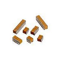
CAP CER 100UF 25V STACKED SMD
Manufacturer
AVX Corporation
Series
TurboCap™r
Specifications of ST203C107MAJ05
Capacitance
100µF
Tolerance
±20%
Temperature Coefficient
X7R
Voltage - Rated
25V
Mounting Type
Surface Mount, MLCC
Operating Temperature
-55°C ~ 125°C
Features
Stacked
Applications
Filtering Switch Mode Power Supplies
Package / Case
10-Stacked SMD, J-Lead
Size / Dimension
0.525" L x 0.300" W (13.34mm x 7.62mm)
Thickness
5.59mm Max
Lead Style
J-Lead
Voltage Rating
25 Volts
Operating Temperature Range
- 55 C to + 125 C
Product
General Type MLCCs
Dielectric Characteristic
X7R
Capacitance Tolerance
± 20%
Capacitor Case Style
DIP
No. Of Pins
10
Capacitor Mounting
SMD
Rohs Compliant
No
Termination Style
Radial
Lead Spacing
6.35 mm
Dimensions
7.62 mm W x 13.34 mm L x 5.59 mm H
Dissipation Factor Df
2.5
Lead Free Status / RoHS Status
Contains lead / RoHS non-compliant
Ratings
-
Lead Spacing
-
Lead Free Status / RoHS Status
Contains lead / RoHS non-compliant
Other names
478-6116


Surface Mounting Guide
MLC Chip Capacitors
PCB BOARD DESIGN
To avoid many of the handling problems, AVX recommends that MLCs be located at least .2" away from nearest edge of
board. However when this is not possible, AVX recommends that the panel be routed along the cut line, adjacent to where the
MLC is located.
COMMON CAUSES OF
MECHANICAL CRACKING
The most common source for mechanical stress is board
depanelization equipment, such as manual breakapart, v-
cutters and shear presses. Improperly aligned or dull cutters
may cause torqueing of the PCB resulting in flex stresses
being transmitted to components near the board edge.
Another common source of flexural stress is contact during
parametric testing when test points are probed. If the PCB is
allowed to flex during the test cycle, nearby ceramic capac-
itors may be broken.
A third common source is board to board connections at
vertical connectors where cables or other PCBs are con-
nected to the PCB. If the board is not supported during the
plug/unplug cycle, it may flex and cause damage to nearby
components.
Special care should also be taken when handling large (>6"
on a side) PCBs since they more easily flex or warp than
smaller boards.
86
Preferred Method - No Direct Part Contact
No Stress Relief for MLCs
Solder Tip
REWORKING OF MLCs
Thermal shock is common in MLCs that are manually
attached or reworked with a soldering iron. AVX strongly
recommends that any reworking of MLCs be done with hot
air reflow rather than soldering irons. It is practically impossi-
ble to cause any thermal shock in ceramic capacitors when
using hot air reflow.
However direct contact by the soldering iron tip often caus-
es thermal cracks that may fail at a later date. If rework by
soldering iron is absolutely necessary, it is recommended
that the wattage of the iron be less than 30 watts and the
tip temperature be <300ºC. Rework should be performed
by applying the solder iron tip to the pad and not directly
contacting any part of the ceramic capacitor.
Routed Cut Line Relieves Stress on MLC
Poor Method - Direct Contact with Part
Solder Tip
Related parts for ST203C107MAJ05
Image
Part Number
Description
Manufacturer
Datasheet
Request
R

Part Number:
Description:
Inverter Grade Thyristors
Manufacturer:
International Rectifier Corp.
Datasheet:

Part Number:
Description:
Manufacturer:
AVX Corporation
Datasheet:
Part Number:
Description:
Manufacturer:
AVX Corporation
Datasheet:
Part Number:
Description:
Manufacturer:
AVX Corporation
Datasheet:
Part Number:
Description:
Manufacturer:
AVX Corporation
Datasheet: