RDER72J104K8K1C11B Murata Electronics North America, RDER72J104K8K1C11B Datasheet - Page 14
RDER72J104K8K1C11B
Manufacturer Part Number
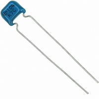
RDER72J104K8K1C11B
Description
CAP CER 100000PF 630V X7R RADIAL
Manufacturer
Murata Electronics North America
Series
RDEr
Datasheets
1.RPEF51H104Z2K1A03B.pdf
(2 pages)
2.RDEE41H104M0K1C03B.pdf
(3 pages)
3.RDER72J682K2K1C11B.pdf
(39 pages)
4.RDER72J104K8K1C11B.pdf
(1 pages)
Specifications of RDER72J104K8K1C11B
Capacitance
0.1µF
Voltage - Rated
630V
Tolerance
±10%
Temperature Coefficient
X7R
Mounting Type
Through Hole
Operating Temperature
-55°C ~ 125°C
Features
High Voltage
Applications
General Purpose
Package / Case
Radial
Size / Dimension
0.217" L x 0.295" W (5.50mm x 7.50mm)
Thickness
4.00mm Max
Lead Spacing
0.197" (5.00mm)
Lead Style
Flat Bent
Lead Free Status / RoHS Status
Lead free / RoHS Compliant
Ratings
-
Other names
490-4821
Available stocks
Company
Part Number
Manufacturer
Quantity
Price
Company:

Part Number:
RDER72J104K8K1C11B
Manufacturer:
PANASONIC
Quantity:
30 000


1
!Note
• This PDF catalog is downloaded from the website of Murata Manufacturing co., ltd. Therefore, it’s specifications are subject to change or our products in it may be discontinued without advance notice. Please check with our
• This PDF catalog has only typical specifications because there is no space for detailed specifications. Therefore, please approve our product specifications or transact the approval sheet for product specifications before ordering.
sales representatives or product engineers before ordering.
!Note
12
No.
10
12 Solderability of Leads
13
14
11
Specifications and Test Methods
Continued from the preceding page.
Terminal
Strength
Vibration
Resistance
Resistance
to
Soldering
Heat
Temperature
and
Immersion
Cycle
• Please read rating and !CAUTION (for storage, operating, rating, soldering, mounting and handling) in this catalog to prevent smoking and/or burning, etc.
• This catalog has only typical specifications because there is no space for detailed specifications. Therefore, please approve our product specifications or transact the approval sheet for product specifications before ordering.
Item
Tensile
Strength
Bending
Strength
Appearance
Capacitance
Q/D.F.
Appearance No defects or abnormalities
Capacitance
Change
Dielectric
Strength
(Between
Terminals)
Appearance No defects or abnormalities
Capacitance
Change
Q/D.F.
Insulation
Resistance
Dielectric
Strength
(Between
Terminals)
Temperature Compensating Type High Dielectric Constant Type
Termination not to be broken or loosened
Termination not to be broken or loosened
No defects or abnormalities
Within the specified tolerance
30pF min. : Q U 1,000
30pF max. : Q U 400+20C
C : Nominal capacitance (pF)
Lead wire should be soldered with uniform coating on the axial
direction over 3/4 of the circumferential direction.
Within T2.5% or T0.25pF
(whichever is larger)
No defects
Within T5% or T0.5pF
(whichever is larger)
30pF min. : Q U 350
10pF to 30pF : Q U 275+5C/2
10pF max. : Q U 200+10C
C : Nominal capacitance (pF)
1,000MΩ or 50MΩ • µF min.
(whichever is smaller)
No defects or abnormalities
Specifications
Char. X7R : 0.025 max.
Char. Y5V : 0.05 max.
Char. X7R : Within T7.5%
Char. Y5V : Within T20%
Char. X7R : Within T12.5%
Char. Y5V : Within T30%
Char. X7R : 0.05 max.
Char. Y5V : 0.075 max.
As in the figure, fix the capacitor body, apply the force
gradually to each lead in the radial direction of the
capacitor until reaching 10N and then keep the force
applied for 10T1 sec.
Each lead wire should be subjected to a force of 2.5N
and then bent 90˚ at the point of egress in one
direction. Each wire is then returned to the original
position and bent 90˚ in the opposite direction at the
rate of one bend per 2 to 3 sec.
The capacitor is soldered securely to a supporting
terminal and a 10 to 55Hz vibration of 1.5mm peak-
peak amplitude is applied for 6 hrs. total, 2 hrs. in each
mutually perpendicular direction. Allow 1 min. to cycle
the frequency from 10Hz to 55Hz and the converse.
The terminal of a capacitor is dipped into a 25% ethanol
(JIS-K-8101) solution of rosin (JIS-K-5902) and
then into molten solder for 2T0.5 sec. In both cases the
depth of dipping is up to about 1.5mm to 2mm from the
terminal body.
Temp. of solder : 245T5˚C Lead Free Solder (Sn-3.0Ag-0.5Cu)
Temp. of solder :
The lead wire is immersed in the melted solder 1.5mm
to 2mm from the main body at 350T10˚C for 3.5T0.5
sec. The specified items are measured after 24T2 hrs.
(temperature compensating type) or 48T4 hrs. (high
dielectric type).
• Initial measurement for high dielectric constant type
The capacitors are heat treated for 1 hr. at 150
allowed to set at room temperature for 48T4 hrs., and
given an initial measurement.
First, repeat the following temperature/time cycle 5
times :
Next, repeat twice the successive cycles of immersion,
each cycle consisting of immersion in a fresh water at
65
aqueous solution of salt at 0T3˚C for 15 min.
The capacitor is then promptly washed in running
water, dried with a drying cloth, and allowed to sit at
room temperature for 24T2 hrs. (temperature
compensating type) or 48T4 hrs. (high dielectric type).
• Initial measurement for high dielectric constant type
The capacitors are heat treated for 1 hr. at
150
T4 hrs., and given an initial measurement.
W5
Y0
lowest operating temperature T3˚C/30T3 min.
ordinary temperature/3 min. max.
highest operating temperature T3˚C/30T3 min.
ordinary temperature/3 min. max.
W 0
Y10
˚C for 15 min. and immersion in a saturated
˚C, allowed to sit at room temperature for 48
235T5˚C H60A or H63A Eutectic Solder
F
Test Method
Continued on the following page.
W 0
Y10
˚C,
C49E.pdf
10.3.8
Related parts for RDER72J104K8K1C11B
Image
Part Number
Description
Manufacturer
Datasheet
Request
R

Part Number:
Description:
BUZZER PIEZO 25VP-P SMD
Manufacturer:
Murata Electronics North America

Part Number:
Description:
CAP 4-ARRAY 680PF 100V X7R 1206
Manufacturer:
Murata Electronics North America
Datasheet:
Part Number:
Description:
CAP 4-ARRAY 1000PF 100V X7R 1206
Manufacturer:
Murata Electronics North America
Datasheet:
Part Number:
Description:
CAP 4-ARRAY 1800PF 100V X7R 1206
Manufacturer:
Murata Electronics North America
Datasheet:
Part Number:
Description:
CAP 4-ARRAY 68000PF 16V X7R 1206
Manufacturer:
Murata Electronics North America
Datasheet:

Part Number:
Description:
CAP CER 1000PF 50V 10% X7R 0402
Manufacturer:
Murata Electronics North America
Datasheet:
Part Number:
Description:
CAP CER 10000PF 16V 10% X7R 0402
Manufacturer:
Murata Electronics North America
Datasheet:

Part Number:
Description:
CAP 5.5-25PF 2.5X3.2MM SMD
Manufacturer:
Murata Electronics North America
Datasheet:

Part Number:
Description:
CAP 4.5-20PF 2.5X3.2MM SMD
Manufacturer:
Murata Electronics North America
Datasheet:

Part Number:
Description:
CAP 5.0-20PF 3.2X4.5MM SMD RED
Manufacturer:
Murata Electronics North America
Datasheet:

Part Number:
Description:
CAP 2.0-6.0PF 3.2X4.5MM SMD BLU
Manufacturer:
Murata Electronics North America
Datasheet:

Part Number:
Description:
CAP 1.4-3.0PF 3.2X4.5MM SMD BRN
Manufacturer:
Murata Electronics North America
Datasheet:

Part Number:
Description:
CAP 3.0-10PF 3.2X4.5MM SMD WHT
Manufacturer:
Murata Electronics North America
Datasheet:

Part Number:
Description:
CAP 2.0-6.0PF 4X4.5MM TOPADJ BLU
Manufacturer:
Murata Electronics North America
Datasheet:

Part Number:
Description:
CAP 8.5-40PF 4X4.5MM TOPADJ YEL
Manufacturer:
Murata Electronics North America
Datasheet: