58330-1 Tyco Electronics, 58330-1 Datasheet - Page 2
58330-1
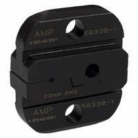
Manufacturer Part Number
58330-1
Description
DIE ASSY U/W A9996-ND
Manufacturer
Tyco Electronics
Series
Pro-Crimper™ IIIr
Type
Dier
Datasheet
1.220189-1.pdf
(5 pages)
Specifications of 58330-1
Connector Type
BNC, TNC
Crimp Handle
A9996-ND
Product
Tool Component
Features
Die for Pro-Crimper
Lead Free Status / RoHS Status
Not applicable / Not applicable
Crimp Or Cable Size
-
Lead Free Status / Rohs Status
Lead free / RoHS Compliant
For Use With
50 Ohm RF Connectors
Other names
A24779


3. DIE INSTALLATION
To be sure that the die assembly is properly aligned
during installation, proceed as follows:
4. CRIMPING PROCEDURE
Select the appropriate die assembly that is
compatible with the connector being used. Proceed
as follows:
4.1. Center Contact
2 of 5
1. Slide the die assembly into the partially--opened
tool jaws. The anvil die must be installed in the
movable jaw of the tool and the indenter in the
stationary jaw. The center contact crimping
chamber must be toward the front of the tool as
shown in Figure 1.
2. Insert, but do not completely tighten, the die
retaining screws.
3. Close the tool jaws and carefully align the dies
so that the anvil die enters the indenter die. Once
the anvil has entered the indenter, place a copper
bus bar (1.57+0.05 mm [.062+.002 in.] diameter)
into the center contact crimping chamber of the die
assembly.
4. With bus bar in place, close the tool jaws
completely. Hold the tool handles together and
tighten the die retaining screws with the
appropriate screwdriver.
NOTE
1. Slide the ferrule onto the cable, then strip the
cable to the proper dimensions.
2. Slide center contact onto center conductor of
cable; then insert contact assembly into the center
contact crimping chamber of the anvil die. See
Figure 2.
NOTE
3. Crimp the center contact by holding the cable in
place; then close the tool handles until the ratchet
releases.
4. Remove the crimped center contact assembly
from the crimping dies.
i
i
For detailed information on cable selection, cable
strip lengths, and proper assembly of the
connector, refer to the instructions provided with
the connector.
Make sure that the flange on the end of the
center contact butts against the edge of the die.
Refer to the cross- - sectional view in Figure 2.
(Figure 2)
4.2. Ferrule
Crimping the
Center Contact
Center Contact
Flange Butt
Against Edge
of Die
Anvil Die
1. Insert the crimped center contact into the
connector body until the cable dielectric butts
against the dielectric inside the connector body.
The flared braid must fit around the support sleeve
of the connector body.
Stripped Cable
Cross- - Sectional
View
Shoulder on
Connector
Body Butts
Against
Edge of Die
Ferrule in
Crimping
Chamber
on Anvil
Die
(Figure 3)
Figure 2
Figure 3
Flange on End of
Center Contact
Edge of Die
408- 2786
Rev J