58062-1 Tyco Electronics, 58062-1 Datasheet - Page 2
58062-1
Manufacturer Part Number
58062-1
Description
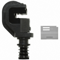
HEAD ASSEMBLY TOOL FOR AMP MT CO
Manufacturer
Tyco Electronics
Series
AMPMODU® MTr
Type
Terminating Head for AMPMODU MT Connectorsr
Datasheet
1.58062-1.pdf
(5 pages)
Specifications of 58062-1
Connector Type
Receptacle
Crimp Handle
A2031-ND, 58075-1-ND, 58338-1-ND, 931800-1-ND
Crimp Or Cable Size
20-30 AWG
Crimp Application
Connectors
Product
Tool Component
For Use With
58075-1 - TOOL HANDLE PNEUMATIC W/O HEAD931800-1 - ELEC PWR UNIT W/O F/TRK OR HD58338-1 - PWR BENCH ASSEMBLY W/O HEADS104305-4 - CONN RCPT 8POS DL IDC .100 GOLD104305-2 - CONN RCPT 34POS DL IDC .100 GOLD104305-1 - CONN RCPT 10POS DL IDC .100 GOLD
Lead Free Status / RoHS Status
Not applicable / Not applicable
Lead Free Status / RoHS Status
na, Not applicable / Not applicable
Other names
A2040


4. TERMINATION PROCEDURE
Make sure that the connector matches the wire size
to be terminated, then refer to Figure 3, and proceed
as follows:
Slide Adapter
Into Slot
2 of 5
Slide Connector
Into Feed Channel
Connector
(Double Row
Shown)
1. Align the side of the connector with the side of
the head (so that it will move in the direction of the
arrow), and slowly slide the connector into the feed
channel. Stop when the desired contact position
aligns with the wire slot.
NOTE
2. Insert the wire into the wire slot until the wire
bottoms on the head.
Ramp
i
(Used for Single- Row Connectors Only)
Clip
Adapter
If the connector cannot be inserted into the head
or if the connector is too loose in the head, refer
to Paragraph 5.2 for wire guide adjustment.
Terminating Connector
Installing Adapter
Wire
Figure 2
Figure 3
Wire
Slot
Power Unit
(Ref)
Tyco Electronics Corporation
5. ADJUSTMENTS
5.1. Wire Insertion Depth
If the wire is inserted too deep or not deep enough in
the contact after termination, adjust the wire insertion
depth as follows:
A. Pneumatic Power Units
Increase the air pressure by 10 psi [69 kPa]. Repeat
the termination and inspection procedure. Continue in
this manner until the proper wire insertion depth is
obtained or the air pressure is set to 70 psi [483 kPa].
If proper wire insertion depth is not obtained at 70 psi
[483 kPa], return the air pressure to 40 psi [276 kPa]
and follow Paragraph B.
DANGER
DANGER
3. Center the wire in the wire slot, then actuate the
power unit until the wire inserter bottoms (the wire
inserter will retract and the connector will advance
to the next contact position).
4. Center the wire in the wire slot, then actuate the
power unit until the wire inserter bottoms (the wire
inserter will retract and the connector will advance
to the next contact position).
5. Repeat Steps 1 through 3 until all applicable
contacts are terminated.
6. Slide the connector out of the head in the
direction of the arrow.
7. Inspect each terminated contact according to
Figure 4. If any contact does not meet the
requirements, DO NOT use the connector. Refer to
Section 5 for adjustments.
NOTE
NOTE
i
i
For application requirements for the connectors,
refer to the appropriate application specification:
114- - 25019 for single- - row connectors and
114- - 25032 for double- - row connectors.
For pneumatic power units, to avoid personal
injury, ALWAYS disconnect the air supply before
making adjustments to the head.
For electric power units, to prevent personal
injury, ALWAYS disconnect the electrical power
supply before making adjustments to the head.
For pneumatic power units, it might be necessary
to adjust either the wire insertion depth or the air
pressure.
Rev B