90548-2 Tyco Electronics, 90548-2 Datasheet - Page 4
90548-2
Manufacturer Part Number
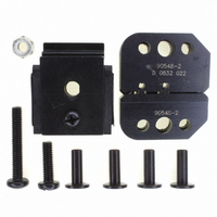
90548-2
Description
TOOL DIESET 18-24AWG UNI-MATE
Manufacturer
Tyco Electronics
Series
MATE-N-LOK II®r
Type
Crimp Tool Assemblyr
Specifications of 90548-2
Connector Type
Crimp Terminals
Crimp Handle
A9996-ND
Crimp Or Cable Size
18-24 AWG
Crimp Tool
Hand Crimper III
Product
Crimping, Stripping & Cutting Tools & Drills
Description/function
Hand crimp tool assembly
For Use With
SDE Dies
Lead Free Status / RoHS Status
Not applicable / Not applicable
Lead Free Status / RoHS Status
na, Not applicable / Not applicable
Other names
A9944


6. CRIMP HEIGHT INSPECTION
Crimp height inspection is performed through the use
of a micrometer with a modified anvil, commonly
referred to as a crimp-height comparator. TE does not
manufacture or market crimp-height comparators.
Detailed information on obtaining and using crimp-
height comparators can be found in instruction sheet
408-7424.
Proceed as follows:
Rev E
Position Point
on Center of
Wire Barrel
Opposite
Seam
5. Insert stripped wire into contact insulation and
wire barrels until it is butted against the wire stop, as
shown in Figure 3.
6. Holding the wire in place, squeeze tool handles
together until ratchet releases. Allow tool handles to
open and remove crimped contact.
7. Check the contact's crimp height as described in
Section 6, Crimp Height Inspection. If necessary,
adjust the crimp height as described in Section 7,
RATCHET (Crimp Height) ADJUSTMENT.
1. Refer to Figure 4 and select a wire (maximum
size) for each crimp section listed.
2. .Refer to Section 5, CRIMPING PROCEDURE,
and crimp the contact(s) accordingly.
3. Using a crimp-height comparator, measure the
wire barrel crimp height as shown in Figure 4. If the
crimp height conforms to that shown in the table,
the tool is considered dimensionally correct. If not,
the tool must be adjusted. Refer to Section 7,
RATCHET (Crimp Height) ADJUSTMENT.
NOTE
AWG (Max)
WIRE SIZE
i
Modified
Anvil
22
18
The crimped contact may stick in the crimping area,
but the contact can be easily removed by pushing
downward on the top of the locator (see Figure 3).
CRIMP SECTION
(Wire Size
Figure 4
Marking)
24-22
20-18
TOLERANCE (±)
CRIMP HEIGHT
DIM “A” AND
[.0385 ± .002]
1.245 ± .0020
[.046 ± .002]
1.02 ± .05
7. RATCHET (Crimp Height) ADJUSTMENT (FIGURE 5)
8. MAINTENANCE
Ensure that the tool and dies are clean by wiping them
with a clean, soft cloth. Remove any debris with a
clean, soft brush. Do not use objects that could
damage the tool. When not in use, keep handles
closed to prevent objects from becoming lodged in the
crimping dies, and store in a clean, dry area.
9. VISUAL INSPECTION
The crimping dies should be inspected on a regular
basis to ensure that they have not become worn or
damaged. Inspect the crimp sections for flattened,
chipped, worn, or broken areas. If damage or
abnormal wear is evident, the tool must be replaced.
See Section 10, REPLACEMENT.
1. Remove the lockscrew from the ratchet
adjustment wheel.
2. With a screwdriver, adjust the ratchet wheel from
the locator side of the tool.
3. Observe the ratchet adjustment wheel. If a tighter
crimp is required, rotate the adjustment wheel
COUNTERCLOCKWISE to a higher-numbered
setting. If a looser crimp is required, rotate the
adjustment wheel CLOCKWISE to a lower-
numbered setting.
4. Replace the lockscrew.
5. Make a sample crimp and measure the crimp
height. If the dimension is acceptable, replace and
secure the lockscrew. If the dimension is
unacceptable, continue to adjust the ratchet, and
again measure a sample crimp.
Ratchet
Adjustment
Wheel
Screwdriver
Lockscrew
(Typ)
Figure 5
408-9885
4 of 6