58423-1 Tyco Electronics, 58423-1 Datasheet - Page 3
58423-1
Manufacturer Part Number
58423-1
Description
DIESET SPLICE TERMINALS
Manufacturer
Tyco Electronics
Series
Pro-Crimper™ IIIr
Type
Crimp Tool Assemblyr
Specifications of 58423-1
Connector Type
Terminals and Splices
Crimp Handle
A9996-ND
Crimp Or Cable Size
10-22 AWG
Die Set, For Insulated Terminals And Splices,cable Wrap,sde Tooling Pro-crimper Iii Hand Tool ,tyco Electronics / Amp
ROHS COMPLIANT
Product
Crimping, Stripping & Cutting Tools & Drills
Lead Free Status / RoHS Status
Not applicable / Not applicable
Lead Free Status / RoHS Status
Not applicable / Not applicable
Other names
A9991


6. CRIMP HEIGHT INSPECTION
This inspection requires the use of calipers. A lead
rod can be used to check the crimp height. Crimp a
rod in each of the crimping chambers. Check the
crimp height of the rod against the crimp height
dimension given in Figure 4.
If the crimp height conforms to the dimension, the tool
and die assembly are considered dimensionally
correct. Lubricate the tool with a thin coat of any good
SAE 20 motor oil. If it does not, adjust the crimp
height according to Section 6. If the adjustment does
not result in acceptable crimp height, the die
assembly or tool may have to be replaced.
7. RATCHET ADJUSTMENT
The tool ratchet mechanism features an adjustment
wheel with numbered settings. The adjustment wheel
controls the amount of handle pressure exerted on
the jaws during crimping. Check the crimp height
according to Section 5. If the crimp height is not
acceptable, adjust the crimp height as follows:
Rev L
Lead Rod
1. Remove the lockscrew from the ratchet
adjustment wheel.
2. With a screwdriver, adjust the ratchet wheel
from the front of the tool.
Diameter
Edge of Terminal
Insulation Aligned
with Edge of Anvil
4.8 [.19]
3.2 [.12]
3.2 [.12]
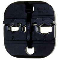
Terminal
Tongue
Anvil
Crimping Chamber
Y (Yellow)
Marking
B (Blue)
R (Red)
Figure 3
Figure 4
(Figure 5)
Tool Jaws
Indenter
3.35+0.15 [.132+.006]
2.44+0.15 [.096+.006]
2.08+0.15 [.082+.006]
Crimp Height
Dimension
Back of Tool
Stripped
Wire
8. MAINTENANCE AND INSPECTION
8.1. Maintenance
Ensure that the tool frame and dies are clean by
wiping them with a clean, soft cloth. Remove any
debris with a clean, soft brush. Do not use objects
that could damage any components. When not in use,
keep tool handles closed to prevent objects from
becoming lodged in the dies, and store in a clean, dry
area.
8.2. Visual Inspection
Inspection of the dies should be made on a regular
basis to ensure that they have not become worn or
damaged. Inspect the crimping chambers for
flattened, chipped, worn, or broken areas. If damage
or abnormal wear is evident, the dies must be
replaced. Refer to Section 8, REPLACEMENT.
9. REPLACEMENT
Customer--replaceable parts are shown in Figure 1.
Available separately, Repair Kit 679221--1 includes a
replacement lock nut and a variety of pins, rings,
screws, and springs. If the dies are damaged or worn
excessively, they must be replaced. Order the repair
kit and replaceable parts through your representative,
or call 1--800--526--5142, or send a facsimile of your
purchase order to 717--986--7605, or write to:
Ratchet Adjustment
Wheel
3. Observe the ratchet adjustment wheel. If a
tighter (smaller) crimp height is required, rotate the
adjustment wheel counterclockwise to a
higher--numbered setting. If a looser (larger) crimp
height is required, rotate the adjustment wheel
clockwise to a lower--numbered setting.
4. Re--assemble the lockscrew.
5. Make a sample crimp. If the crimp height is
acceptable, the adjustment setting is correct. If the
crimp height is unacceptable, continue to adjust
the ratchet, and again measure a sample crimp.
Screwdriver
Lockscrew
Figure 5
408- 9252
3 of 4