58517-1 Tyco Electronics, 58517-1 Datasheet - Page 4
58517-1
Manufacturer Part Number
58517-1
Description
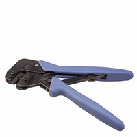
TOOL CRIMP W/DIE CST-100
Manufacturer
Tyco Electronics
Series
Pro-Crimper™ IIIr
Type
Hand Tool Assemblyr
Specifications of 58517-1
Tool Type
Hand Crimper
Features
Side Entry, Ratchet
Rohs Compliant
NA
Product
Crimping, Stripping & Cutting Tools & Drills
Lead Free Status / RoHS Status
Not applicable / Not applicable
For Use With/related Products
Rectangular Contacts, 22-26 AWG
For Use With
1445336-3 - CONTACT CST-100 II 26-22AWG 30AU1445336-2 - CONTACT CST-100 II 26-22AWG 15AUA99620 - CONN SCKT 26-22AWG TIN CST100 IIA23962 - CONN SOCKET 22-26AWG GOLD CRIMPA19520 - CONN TERM CRIMP CST-100 TIN
Lead Free Status / Rohs Status
Lead free / RoHS Compliant
Other names
A19530


Rev E
.
6. CRIMP HEIGHT INSPECTION
Proceed as follows:
7. .CRIMP HEIGHT ADJUSTMENT
Crimp height inspection is performed through the
use of a micrometer with a modified anvil,
commonly referred to as a crimp height comparator.
Tyco Electronics does not market crimp height
comparators. Refer to Instruction Sheet 408-7224
for detailed information on obtaining and using a
crimp height comparator.
1. Refer to Figure 4 and select a wire (maximum
size) for the crimp section.
2. Refer to Section 4, CRIMPING PROCEDURE,
and crimp the contact(s) accordingly.
3. Using a crimp height comparator, measure the
wire barrel crimp height as shown in Figure 4. If
the crimp height conforms to that shown in the
table, the tool is considered dimensionally
correct. If not, the tool must be adjusted. Refer to
Section 7, CRIMP HEIGHT ADJUSTME
1. Remove the lockscrew from the ratchet
adjustment wheel.
2. With a screwdriver, adjust the ratchet wheel
from the locator side of the tool.
3. Observe the ratchet adjustment wheel. If a
tighter crimp is required, rotate the adjustment
wheel COUNTERCLOCKWISE to a higher-
numbered setting. If a looser crimp is required,
rotate the adjustment wheel CLOCKWISE to a
lower-numbered setting.
4. Replace the lockscrew.
5. Make a sample crimp and measure the crimp
height. If the dimension is acceptable, replace
and secure the lockscrew. If the dimension is
unacceptable, continue to adjust the ratchet, and
again measure a sample crimp.
AWG (Max)
WIRE SIZE
22
CRIMP SECTION
(WIRE SIZE
MARKING)
Figure 4
26-22
(Figure 5)
TOLERANCE (±)
CRIMP HEIGHT
DIM (A) AND
[.031±.002]
0.79±0.05
8. MAINTENANCE
Ensure that the tool and dies are clean by wiping them
with a clean, soft cloth. Remove any debris with a
clean, soft brush. Do not use objects that could
damage the tool. When not in use, keep handles
closed to prevent objects from becoming lodged in the
crimping dies, and store in a clean, dry area.
9. VISUAL INSPECTION
The crimping dies should be inspected on a regular
basis to ensure that they have not become worn or
damaged. Inspect the crimp section for flattened,
chipped, worn, or broken areas. If damage or
abnormal wear is evident, the tool must be replaced.
See Section 10, REPLACEMENT.
10. REPLACEMENT
Customer-replaceable parts are shown in Figure 1.
Available separately, PRO-CRIMPER III Hand Tool
Repair Kit 679221-1 includes a replacement nut and a
variety of pins, rings, screws, and springs. If the dies
are damaged or worn excessively, they must be
replaced. Order the repair kit and replaceable parts
through your TE representative, or call 1-800-526-
5142, or send a facsimile of your purchase order to 1-
717-986-7605, or write to:
11. REVISION SUMMARY
Since the previous release of this sheet, the following
changes were made:
•
•
CUSTOMER SERVICE (038-035)
TYCO ELECTRONICS CORPORATION
PO BOX 3608
HARRISBURG PA 17105-3608
Corrected callouts in Figure 3
Document updated to corporate requirements
Ratchet
Adjustment
Pawl
Lockscrew
Screwdriver
Figure 5
408-4064
4 of 5