91388-1 Tyco Electronics, 91388-1 Datasheet - Page 4
91388-1
Manufacturer Part Number
91388-1
Description
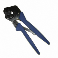
TOOL CRIMP 4.2MM PE 18-22AWG
Manufacturer
Tyco Electronics
Series
Pro-Crimper™ III, VAL-U-LOK™r
Type
Crimpersr
Specifications of 91388-1
Tool Type
Hand Crimper
Features
Side Entry, Ratchet
Product
Crimping, Stripping & Cutting Tools & Drills
Description/function
Pro-Crimper and die
Fits Cable/wire
22-18 AWG
For Use With/related Products
Rectangular Contacts, 18-22 AWG
For Use With
A30653 - CONN TERM PIN 18-22AWG 30GOLDA30652 - CONN TERM PIN 18-22AWG TINA30651 - CONN TERM PIN 18-22AWG 30GOLDA30650 - CONN TERM PIN 18-22AWG TINA30645 - CONN TERM SOCKET 18-22AWG 30GOLDA30644 - CONN TERM SOCKET 18-22AWG TINA30643 - CONN TERM SOCKET 18-22AWG 30GOLDA30642 - CONN TERM SOCKET 18-22AWG TIN
Lead Free Status / RoHS Status
Not applicable / Not applicable
Other names
A30667


4 of 5
CAUTION
[.173]
4.39
4. Hold the contact in position and squeeze the
tool handles together until ratchet engages
sufficiently to hold the contact in position. Do NOT
deform insulation barrel or wire barrel.
5. Insert stripped wire into contact insulation and
wire barrels until it is butted against the wire stop,
as shown in Figure 3.
6. Holding the wire in place, squeeze tool handles
together until ratchet releases. Allow tool handles
to open and remove crimped contact.
NOTE
7. Check the contact’s crimp height as described in
Section 6, CRIMP HEIGHT INSPECTION. If
necessary, adjust the crimp height as described in
Section 7, CRIMP HEIGHT ADJUSTMENT.
[.188]
4.78
i
!
11
Adjustment
Screw for
Contact
Support
The crimped contact may stick in the crimping
area, but the contact can be easily removed by
pushing downward on the top of the locator (see
Figure 3).
Damaged contacts may not be used. If a
damaged contact is evident, it must be cut from
the wire and replace with a new one.
Contact
Support
Locator
Figure 3
Back of Tool
(Wire Side)
6. CRIMP HEIGHT INSPECTION
This inspection requires the use of a micrometer with
a modified anvil. TE recommends the modified
micrometer (Crimp Height Comparator
RS--1019--5LP) which may be purchased from:
Proceed as follows:
Shearer Industrial Supply Co.
717- -767- -7575
1. Refer to Figure 4 and select a wire (maximum
size) for each crimp section listed.
2. Refer to Section 5, CRIMPING PROCEDURE,
and crimp the contact(s) accordingly.
3. Using a crimp height comparator, measure the
wire barrel crimp height as shown in Figure 4. If the
crimp height conforms to that shown in the table,
the tool is considered dimensionally correct. If not,
the tool must be adjusted. Refer to Section 7,
CRIMP HEIGHT ADJUSTMENT.
Wire
Contact
(Typ)
Locator
in Wire
Stop Slot
or
VALCO
610- -691- -3205
Wire Inserted
to Stop
Strip Length
408- 8918
Rev A