58514-1 Tyco Electronics, 58514-1 Datasheet - Page 4
58514-1
Manufacturer Part Number
58514-1
Description
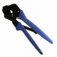
PROCRIMP TL W/DIE MR18-26
Manufacturer
Tyco Electronics
Series
Pro-Crimper™ III, MRr
Type
Crimp Toolr
Datasheet
1.58514-1.pdf
(6 pages)
Specifications of 58514-1
Tool Type
Hand Crimper
Features
Side Entry, Ratchet
Rohs Compliant
NA
Product
Crimping, Stripping & Cutting Tools & Drills
Description/function
PRO-CRIMPER III Hand Tool
Lead Free Status / RoHS Status
Not applicable / Not applicable
For Use With/related Products
Rectangular Contacts, 18-26 AWG
For Use With
350666-1 - CONN SOCKET 18-26AWG CRIMP TINA25442 - CONN PIN GRND 18-26AWG TIN CRIMPA25445 - CONN SOCKET 24-26AWG GOLD CRIMPA25441 - CONN SOCKET 24-26AWG TIN CRIMPA25444 - CONN PIN 24-26AWG GOLD CRIMPA25446 - CONN PIN 18-26AWG GOLD CRIMPA25440 - CONN PIN 24-26AWG TIN CRIMPA14196 - CONN SOCKET 18-26AWG GOLD CRIMPA14197 - CONN SOCKET 18-26AWG TIN CRIMPA14198 - CONN PIN 18-26AWG GOLD CRIMPA14199 - CONN PIN 18-26AWG TIN CRIMP
Lead Free Status / Rohs Status
Lead free / RoHS Compliant
Other names
58514-1
A25448
A25448


6. CRIMP HEIGHT INSPECTION
RATCHETCrimp height inspection is performed
through the use of a micrometer with a modified anvil,
commonly referred to as a crimp--height comparator.
Tyco Electronics does not manufacture or market
crimp--height comparators. Detailed information on
obtaining and using crimp--height comparators can be
found in instruction sheet 408--7424.
Proceed as follows:
7. RATCHET (Crimp Height) ADJUSTMENT
4 of 6
4. Hold the contact in position and squeeze the
tool handles together until ratchet engages
sufficiently to hold the contact in position. Do NOT
deform insulation barrel or wire barrel.
5. Insert stripped wire into contact insulation and
wire barrels until it is butted against the wire stop,
as shown in Figure 3.
6. Holding the wire in place, squeeze tool handles
together until ratchet releases. Allow tool handles
to open and remove crimped contact.
NOTE
7. Check the contact’s crimp height as described in
Section 6, CRIMP HEIGHT INSPECTION. If
necessary, adjust the crimp height as described in
Section 7, RATCHET (Crimp Height)
ADJUSTMENT.
1. Refer to Figure NO TAG and select a wire
(maximum size) for each crimp section listed.
2. Refer to Section 5, CRIMPING PROCEDURE,
and crimp the contact(s) accordingly.
3. Using a crimp height comparator, measure the
wire barrel crimp height as shown in Figure 4. If the
crimp height conforms to that shown in the table,
the tool is considered dimensionally correct. If not,
the tool must be adjusted. Refer to Section 7,
RATCHET (Crimp Height) ADJUSTMENT.
1. Remove the lockscrew from the ratchet
adjustment wheel.
2. With a screwdriver, adjust the ratchet wheel
from the locator side of the tool (see Figure 5).
i
The crimped contact may stick in the crimping
area, but the contact can be easily removed by
pushing downward on the top of the locator (see
Figure 3).
Tyco Electronics Corporation
8. MAINTENANCE
Ensure that the tool and dies are clean by wiping
them with a clean, soft cloth. Remove any debris with
Position Point
on Center of
Wire Barrel
Opposite
Seam
Modified Anvil
AWG (Max)
Wire Size
Wire Size
3. Observe the ratchet adjustment wheel. If a
tighter crimp is required, rotate the adjustment
wheel COUNTERCLOCKWISE to a
higher--numbered setting. If a looser crimp is
required, rotate the adjustment wheel
CLOCKWISE to a lower--numbered setting.
4. Replace the lockscrew.
5. Make a sample crimp and measure the crimp
height. If the dimension is acceptable, replace and
secure the lockscrew. If the dimension is
unacceptable, continue to adjust the ratchet, and
again measure a sample crimp.
Ratchet
Adjustment
Wheel
22
24
18
Screwdriver
Lockscrew
(Typ)
(Wire Size Marking)
Crimp Section
Crimp Section
26--22
26--24
20--18
Figure 5
Figure 4
“A”
Dimension A and
Dimension A and
Crimp Height
Tolerance (+)
[.028 .002]
[.038 .002]
.71 .05
.71 .05
.97 .05
Rev B