752161473GPTR CTS Resistor Products, 752161473GPTR Datasheet - Page 11
752161473GPTR
Manufacturer Part Number
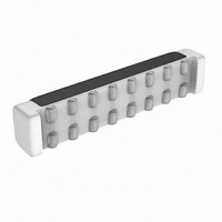
752161473GPTR
Description
RES-NET 47K OHM BUSSED SMD
Manufacturer
CTS Resistor Products
Series
752r
Specifications of 752161473GPTR
Resistance (ohms)
47K
Number Of Resistors
14
Circuit Type
Bussed
Temperature Coefficient
±200ppm/°C
Tolerance
±2%
Power Per Element
80mW
Number Of Pins
16
Package / Case
16-DRT
Size / Dimension
0.465" L x 0.080" W (11.81mm x 2.03mm)
Height
0.095" (2.41mm)
Mounting Type
Surface Mount
Operating Temperature
-55°C ~ 125°C
Lead Free Status / RoHS Status
Lead free / RoHS Compliant
Other names
752-161-47KPTR


Typical Performance Characteristics
Application Information
BRIDGE CONFIGURATION EXPLANATION
The Audio Amplifier portion of the LM4805 has two internal
amplifiers allowing different amplifier configurations. The first
amplifier’s gain is externally configurable, whereas the sec-
ond amplifier is internally fixed in a unity-gain, inverting
configuration. The closed-loop gain of the first amplifier is set
by selecting the ratio of Rf to Ri while the second amplifier’s
gain is fixed by the two internal 20kΩ resistors. Figure 1
shows that the output of amplifier one serves as the input to
amplifier two. This results in both amplifiers producing sig-
nals identical in magnitude, but out of phase by 180˚. Con-
sequently, the differential gain for the Audio Amplifier is
By driving the load differentially through outputs VO1 and
VO2, an amplifier configuration commonly referred to as
“bridged mode” is established. Bridged mode operation is
different from the classic single-ended amplifier configura-
tion where one side of the load is connected to ground.
A bridge amplifier design has a few distinct advantages over
the single-ended configuration. It provides differential drive
Maximum Duty Cycle
vs Temperature - ”X”
A
VD
R
= 2 *(Rf/Ri)
vs V
DS
(ON)
DD
20126248
20126245
11
(Continued)
to the load, thus doubling the output swing for a specified
supply voltage. Four times the output power is possible as
compared to a single-ended amplifier under the same con-
ditions. This increase in attainable output power assumes
that the amplifier is not current limited or clipped. In order to
choose an amplifier’s closed-loop gain without causing ex-
cessive clipping, please refer to the Audio Power Amplifier
Design section.
The bridge configuration also creates a second advantage
over single-ended amplifiers. Since the differential outputs,
VO1 and VO2, are biased at half-supply, no net DC voltage
exists across the load. This eliminates the need for an output
coupling capacitor which is required in a single supply,
single-ended amplifier configuration. Without an output cou-
pling capacitor, the half-supply bias across the load would
result in both increased internal IC power dissipation and
also possible loudspeaker damage.
AMPLIFIER POWER DISSIPATION
Power dissipation is a major concern when designing a
successful amplifier, whether the amplifier is bridged or
single-ended. A direct consequence of the increased power
delivered to the load by a bridge amplifier is an increase in
internal power dissipation. Since the amplifier portion of the
LM4805 has two operational amplifiers, the maximum inter-
vs Temperature
R
DS
(ON)
20126247
www.national.com
Related parts for 752161473GPTR
Image
Part Number
Description
Manufacturer
Datasheet
Request
R

Part Number:
Description:
RESISTOR NET 4.7K OHM SMD
Manufacturer:
CTS Resistor Products
Datasheet:

Part Number:
Description:
RES .10 OHM 1/8W 5% 0805
Manufacturer:
CTS Resistor Products
Datasheet:

Part Number:
Description:
RES .20 OHM 1/10W 5% 0402
Manufacturer:
CTS Resistor Products
Datasheet:

Part Number:
Description:
RES .47 OHM 1/8W 5% 0805
Manufacturer:
CTS Resistor Products
Datasheet:

Part Number:
Description:
RES .47 OHM 1/10W 5% 0402
Manufacturer:
CTS Resistor Products
Datasheet:

Part Number:
Description:
RES .47 OHM 1/4W 5% 1206
Manufacturer:
CTS Resistor Products
Datasheet:

Part Number:
Description:
RES .20 OHM 1/10W 5% 0603
Manufacturer:
CTS Resistor Products
Datasheet:

Part Number:
Description:
RES .47 OHM 1/2W 5% 1210
Manufacturer:
CTS Resistor Products
Datasheet:

Part Number:
Description:
RES .20 OHM 1/2W 5% 1210
Manufacturer:
CTS Resistor Products
Datasheet:

Part Number:
Description:
RES .47 OHM .75W 5% 2010
Manufacturer:
CTS Resistor Products
Datasheet:

Part Number:
Description:
RES .20 OHM .75W 5% 2010
Manufacturer:
CTS Resistor Products
Datasheet:

Part Number:
Description:
RES .56 OHM .75W 5% 2010
Manufacturer:
CTS Resistor Products
Datasheet:

Part Number:
Description:
RES .91 OHM .75W 5% 2010
Manufacturer:
CTS Resistor Products
Datasheet:

Part Number:
Description:
RES .050 OHM .5W 5% 1206
Manufacturer:
CTS Resistor Products
Datasheet:

Part Number:
Description:
RES NET 15RES 4.7K OHM 16PIN SMD
Manufacturer:
CTS Resistor Products
Datasheet: