TAJA225M006RNJ AVX Corporation, TAJA225M006RNJ Datasheet - Page 15
TAJA225M006RNJ
Manufacturer Part Number
TAJA225M006RNJ
Description
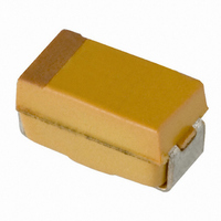
CAP TANTALUM 2.2UF 6.3V 20% SMD
Manufacturer
AVX Corporation
Series
TAJr
Type
Moldedr
Specifications of TAJA225M006RNJ
Capacitance
2.2µF
Voltage - Rated
6.3V
Tolerance
±20%
Esr (equivalent Series Resistance)
9.000 Ohm
Operating Temperature
-55°C ~ 125°C
Mounting Type
Surface Mount
Package / Case
1206 (3216 Metric)
Size / Dimension
0.126" L x 0.063" W (3.20mm x 1.60mm)
Height
0.063" (1.60mm)
Manufacturer Size Code
A
Features
General Purpose
Capacitance Tolerance
± 20%
Voltage Rating
6.3VDC
Capacitor Case Style
1206
No. Of Pins
2
Operating Temperature Range
-55°C To +125°C
Capacitor Mounting
SMD
Reel Quantity
2000
Rohs Compliant
Yes
Dimensions
1.6 mm W x 3.2 mm L
Mfr Case Code
A Case
Product
Tantalum Solid Standard Grade - Other Various
Termination Style
SMD/SMT
Lead Free Status / RoHS Status
Lead free / RoHS Compliant
Lead Spacing
-
Lead Free Status / Rohs Status
Compliant
Other names
478-3862-2
TAJA225M006R
TAJA225M006R
Available stocks
Company
Part Number
Manufacturer
Quantity
Price
Company:

Part Number:
TAJA225M006RNJ
Manufacturer:
AVX Corporation
Quantity:
34 524
Part Number:
TAJA225M006RNJ
Manufacturer:
AVX
Quantity:
20 000


Technical Summary and
Application Guidelines
The heat generated inside a tantalum capacitor in a.c.
operation comes from the power dissipation due to ripple
current. It is equal to I
current at a given frequency, and R is the ESR at the same
frequency with an additional contribution due to the leakage
current. The heat will be transferred from the outer surface by
conduction. How efficiently it is transferred from this point is
dependent on the thermal management of the board.
The power dissipation ratings given in Section 2.1 are based
on free-air calculations. These ratings can be approached if
efficient heat sinking and/or forced cooling is used.
2.2 Thermal Management
2
R, where I is the rms value of the
LEAD FRAME
Thermal Impedance Graph with Ripple Current
140
120
100
SOLDER
80
60
40
20
0
Thermal Dissipation from the Mounted Chip
= PCB MAX Cu THERMAL
0
TEMPERATURE DEG C
0.1 0.2 0.3
236 C\WATT
X
X - RESULTS OF RIPPLE CURRENT TEST - RESIN BODY
X
X
POWER IN UNIT CASE, DC WATTS
C CASE SIZE CAPACITOR BODY
THERMAL IMPEDANCE GRAPH
0.4
PRINTED CIRCUIT BOARD
0.5 0.6
TANTALUM
ANODE
= PCB MIN Cu AIR GAP
121 C\WATT
0.7 0.8 0.9
In practice, in a high density assembly with no specific
thermal management, the power dissipation required to give
a 10°C rise above ambient may be up to a factor of 10
less. In these cases, the actual capacitor temperature should
be established (either by thermocouple probe or infra-red
scanner) and if it is seen to be above this limit it may
be necessary to specify a lower ESR part or a higher
voltage rating.
Please contact application engineering for details or contact
the AVX technical publication entitled “Thermal Management
of Surface Mounted Tantalum Capacitors” by Ian Salisbury.
1.0
73 C\WATT
1.1 1.2 1.3
= CAP IN FREE AIR
ENCAPSULANT
1.4
COPPER
43
Related parts for TAJA225M006RNJ
Image
Part Number
Description
Manufacturer
Datasheet
Request
R

Part Number:
Description:
Manufacturer:
AVX Corporation
Datasheet:
Part Number:
Description:
Manufacturer:
AVX Corporation
Datasheet:
Part Number:
Description:
Manufacturer:
AVX Corporation
Datasheet:
Part Number:
Description:
Manufacturer:
AVX Corporation
Datasheet:
Part Number:
Description:
Manufacturer:
AVX Corporation
Datasheet: