TAJA225M006RNJ AVX Corporation, TAJA225M006RNJ Datasheet - Page 10
TAJA225M006RNJ
Manufacturer Part Number
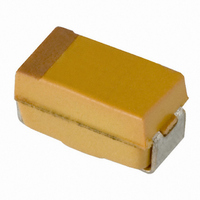
TAJA225M006RNJ
Description
CAP TANTALUM 2.2UF 6.3V 20% SMD
Manufacturer
AVX Corporation
Series
TAJr
Type
Moldedr
Specifications of TAJA225M006RNJ
Capacitance
2.2µF
Voltage - Rated
6.3V
Tolerance
±20%
Esr (equivalent Series Resistance)
9.000 Ohm
Operating Temperature
-55°C ~ 125°C
Mounting Type
Surface Mount
Package / Case
1206 (3216 Metric)
Size / Dimension
0.126" L x 0.063" W (3.20mm x 1.60mm)
Height
0.063" (1.60mm)
Manufacturer Size Code
A
Features
General Purpose
Capacitance Tolerance
± 20%
Voltage Rating
6.3VDC
Capacitor Case Style
1206
No. Of Pins
2
Operating Temperature Range
-55°C To +125°C
Capacitor Mounting
SMD
Reel Quantity
2000
Rohs Compliant
Yes
Dimensions
1.6 mm W x 3.2 mm L
Mfr Case Code
A Case
Product
Tantalum Solid Standard Grade - Other Various
Termination Style
SMD/SMT
Lead Free Status / RoHS Status
Lead free / RoHS Compliant
Lead Spacing
-
Lead Free Status / Rohs Status
Compliant
Other names
478-3862-2
TAJA225M006R
TAJA225M006R
Available stocks
Company
Part Number
Manufacturer
Quantity
Price
Company:

Part Number:
TAJA225M006RNJ
Manufacturer:
AVX Corporation
Quantity:
34 524
Part Number:
TAJA225M006RNJ
Manufacturer:
AVX
Quantity:
20 000


Technical Summary and
Application Guidelines
It is important to ensure that the voltage across the terminals
of the capacitor never exceeds the specified surge voltage
rating.
Solid tantalum capacitors have a self healing ability provided
by the Manganese Dioxide semiconducting layer used as the
negative plate. However, this is limited in low impedance
applications.
In the case of low impedance circuits, the capacitor is likely
to be stressed by current surges. Derating the capacitor by
50% or more increases the reliability of the component. (See
Figure 2 page 45). The “AVX Recommended Derating Table”
(page 46) summarizes voltage rating for use on common
voltage rails, in low impedance applications.
In circuits which undergo rapid charge or discharge a pro-
tective resistor of 1 /V is recommended. If this is impossible,
a derating factor of up to 70% should be used.
In such situations a higher voltage may be needed than is
available as a single capacitor. A series combination should
be used to increase the working voltage of the equivalent
capacitor: For example two 22µF 25V parts in series is equiv-
alent to one 11µF 50V part. For further details refer to J.A.
Gill’s paper “Investigation into the effects of connecting
Tantalum capacitors in series”, available from AVX offices
worldwide.
NOTE:
While testing a circuit (e.g. at ICT or functional) it is likely that
the capacitors will be subjected to large voltage and current
transients, which will not be seen in normal use. These con-
ditions should be borne in mind when considering the
capacitor’s rated voltage for use. These can be controlled by
ensuring a correct test resistance is used.
1.2.5 Reverse voltage and Non-Polar operation.
The values quoted are the maximum levels of reverse voltage
which should appear on the capacitors at any time. These
limits are based on the assumption that the capacitors are
polarized in the correct direction for the majority of their
working life. They are intended to cover short term reversals
of polarity such as those occurring during switching tran-
sients of during a minor portion of an impressed waveform.
Continuous application of reverse voltage without normal
polarization will result in a degradation of leakage current. In
conditions under which continuous application of a reverse
voltage could occur two similar capacitors should be used in
a back-to-back configuration with the negative terminations
connected together. Under most conditions this combination
will have a capacitance one half of the nominal capacitance
of either capacitor. Under conditions of isolated pulses or
during the first few cycles, the capacitance may approach
the full nominal value.
The reverse voltage ratings are designed to cover exception-
al conditions of small level excursions into incorrect polarity.
The values quoted are not intended to cover continuous
reverse operation.
The peak reverse voltage applied to the capacitor must not
exceed:
38
1.2.6 Superimposed A.C. Voltage (Vr.m.s.) -
This is the maximum r.m.s. alternating voltage; superim-
posed on a d.c. voltage, that may be applied to a capacitor.
The sum of the d.c. voltage and peak value of the
super-imposed a.c. voltage must not exceed the category
voltage, Vc.
Full details are given in Section 2.
1.2.7 Forming voltage.
This is the voltage at which the anode oxide is formed. The
thickness of this oxide layer is proportional to the formation
voltage for a tantalum capacitor and is a factor in setting the
rated voltage.
1.3 DISSIPATION FACTOR AND
1.3.1 Dissipation factor (D.F.).
Dissipation factor is the measurement of the tangent of the
loss angle (tan ) expressed as a percentage. The measure-
ment of DF is carried out using a measuring bridge which
supplies a 0.5Vpk-pk 120Hz sinusoidal signal, free of har-
monics with a maximum bias of 2.2Vdc. The value of DF is
temperature and frequency dependent.
Note: For surface mounted products the maximum allowed
DF values are indicated in the ratings table and it is important
to note that these are the limits met by the component
AFTER soldering onto the substrate.
1% of the category d.c. working voltage to a maximum of
10% of the rated d.c. working voltage to a maximum of
3% of the rated d.c. working voltage to a maximum of
TANGENT OF LOSS ANGLE (TAN )
Ripple Voltage.
-10
10
-2
-4
-6
-8
4
8
6
2
0
LEAKAGE CURRENT vs. BIAS VOLTAGE
-20
0
TAJD336M006
TAJD476M010
0.1v at 125°C
1.0v at 25°C
0.5v at 85°C
20
Applied Voltage (Volts)
40
60
TAJC685M020
TAJD336M016
80
100
Related parts for TAJA225M006RNJ
Image
Part Number
Description
Manufacturer
Datasheet
Request
R

Part Number:
Description:
Manufacturer:
AVX Corporation
Datasheet:
Part Number:
Description:
Manufacturer:
AVX Corporation
Datasheet:
Part Number:
Description:
Manufacturer:
AVX Corporation
Datasheet:
Part Number:
Description:
Manufacturer:
AVX Corporation
Datasheet:
Part Number:
Description:
Manufacturer:
AVX Corporation
Datasheet: