H3CR-A8E AC100-240/DC100-125 Omron, H3CR-A8E AC100-240/DC100-125 Datasheet - Page 5
H3CR-A8E AC100-240/DC100-125
Manufacturer Part Number
H3CR-A8E AC100-240/DC100-125
Description
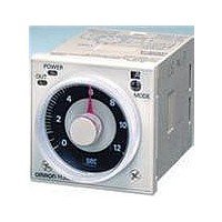
RELAY ANALOG SET DPDT 8PIN
Manufacturer
Omron
Series
H3CR-Ar
Datasheets
1.H3CR-A8_AC24-48DC12-48.pdf
(21 pages)
2.H3CR-A-AC100-240DC100-125.pdf
(29 pages)
3.H3CR-A_AC100-240DC100-125.pdf
(22 pages)
Specifications of H3CR-A8E AC100-240/DC100-125
Mounting Type
Socket
Relay Type
Integrated
Function
Programmable (Multi-Function)
Circuit
DPDT (2 Form C)
Delay Time
0.05 Sec ~ 300 Hrs
Output Type
Mechanical Relay
Contact Rating @ Voltage
5A @ 250VAC
Voltage - Supply
100 ~ 240VAC, 100 ~ 125VDC
Termination Style
8 Pin Socketable
Timing Adjustment Method
Hand Dial
Timing Initiate Method
Input Voltage
Timing Range
0.05 s to 300 Hrs
Supply Voltage
100 VAC to 240 VAC, 100 VDC to 125 VDC
Accuracy
+/- 0.2 %
Current Rating (max)
5 A
Display Type
Hand Dial
Operating Temperature Range
- 10 C to + 55 C
Time Range
0.05 Sec. To 300 Hr.
Supply Voltage Ac, Min
100VAC
No. Of Timing Functions
4
Body Material
94B3297
No. Of Pins
8
Supply Voltage Ac, Max
240VAC
Load Current Rms Max
5A
Rohs Compliant
Yes
Lead Free Status / RoHS Status
Lead free / RoHS Compliant
Lead Free Status / RoHS Status
Lead free / RoHS Compliant, Lead free / RoHS Compliant
Other names
H3CR-A8EAC100-240/DC100-125
H3CRA8EAC100240DC100125
H3CRA8EAC100240DC100125
Q3619148
H3CRA8EAC100240DC100125
H3CRA8EAC100240DC100125
Q3619148


■ Characteristics
Note: 1. The value is ±5% FS +100 ms to −0 ms max. when the C, D, or G mode signal of the H3CR-AP is OFF.
■ Life-test Curve
Accuracy of operating
time
Setting error
Reset time
Reset voltage
Influence of voltage
Influence of temperature ±1% FS max. (±1%±10 ms max. in a range of 1.2 s or 3 s)
Insulation resistance
Dielectric strength
Impulse withstand
voltage
Noise immunity
Static immunity
Vibration resistance
Shock resistance
Ambient temperature
Ambient humidity
Life expectancy
EMC
Case color
Degree of protection
Weight
10,000
5,000
1,000
2. Refer to the Life-test Curve.
500
100
250 VAC (cosφ = 0.4)
Load current (A)
30 VDC L/R = 7 ms
±0.2% FS max. (±0.2%±10 ms max. in a range of 1.2 s or 3 s)
±5% FS ±50 ms (See note 1)
Min. power-opening time: 0.1 s max.
Min. pulse width:
10% max. of rated supply voltage
±0.2% FS max. (±0.2%±10 ms max. in a range of 1.2 s or 3 s)
100 MΩ min. (at 500 VDC)
2,000 VAC (1,000 VAC for H3CR-A@S), 50/60 Hz for 1 min (between current-carrying metal parts and exposed non-
current-carrying metal parts)
2,000 VAC (1,000 VAC for H3CR-A@S), 50/60 Hz for 1 min (between control output terminals and operating circuit)
2,000 VAC, 50/60 Hz for 1 min (between contacts of different polarities)
1,000 VAC, 50/60 Hz for 1 min (between contacts not located next to each other)
2,000 VAC, 50/60 Hz for 1 min (between input and control output terminals and operation circuit) for H3CR-AP
3 kV (between power terminals) for 100 to 240 VAC/100 to 125 VDC, 1 kV for 24 to 48 VAC/12 to 48 VDC
4.5 kV (between current-carrying terminal and exposed non-current-carrying metal parts) for 100 to 240 VAC/100 to
125 VDC, 1.5 kV for 24 to 48 VAC/12 to 48 VDC and 24 to 48 VAC/VDC
±1.5 kV (between power terminals) and ±600 V (between no-voltage input terminals), square-wave noise by noise
simulator (pulse width: 100 ns/1 µs, 1-ns rise)
Malfunction: 8 kV
Destruction: 15 kV
Destruction: 10 to 55 Hz with 0.75-mm single amplitude each in 3 directions for 2 hours each
Malfunction: 10 to 55 Hz with 0.5-mm single amplitude each in 3 directions for 10 minutes each
Destruction: 1,000 m/s
Malfunction: 100 m/s
Operating:
Storage:
Operating:
Mechanical: 20,000,000 operations min. (under no load at 1,800 operations/h)
Electrical:
(EMI)
Emission Enclosure:
Emission AC Mains:
(EMS)
Immunity ESD:
Immunity RF-interference from AM Radio Waves:
Immunity RF-interference from Pulse-modulated Radio Waves:IEC61000-4-3: 10 V/m (900±5 MHz) (level 3)
Immunity Conducted Disturbance: IEC61000-4-6:
Immunity Burst:
Immunity Surge:
Light gray (Munsell 5Y7/1)
IP40 (panel surface)
Approx. 90 g
250 VAC/30 VDC
(cosφ = 1)
−10°C to 55°C (with no icing)
−25°C to 65°C (with no icing)
35% to 85%
100,000 operations min. (5 A at 250 VAC, resistive load at 1,800 operations/h) (See note 2)
2
3 times each in 6 directions
2
3 times each in 6 directions
Reference: A maximum current of 0.15 A can be switched at 125 VDC (cosφ = 1)
0.05 s (H3CR-A/-AS)
EN61812-1
EN55011 Group 1 class A
EN55011 Group 1 class A
EN61812-1
IEC61000-4-2:
IEC61000-4-4:
IEC61000-4-5:
and a maximum current of 0.1 A can be switched if L/R is 7 ms. In
both cases, a life of 100,000 operations can be expected.
The minimum applicable load is 10 mA at 5 VDC (failure level: P).
6 kV contact discharge (level 3)
8 kV air discharge (level 3)
IEC61000-4-3: 10 V/m (80 MHz to 1 GHz) (level 3)
10 V (0.15 to 80 MHz) (level 3)
2 kV power-line (level 3)
2 kV I/O signal-line (level 4)
1 kV line to line (level 3)
2 kV line to ground (level 3)
H3CR-A
5
Related parts for H3CR-A8E AC100-240/DC100-125
Image
Part Number
Description
Manufacturer
Datasheet
Request
R

Part Number:
Description:
G6S-2GLow Signal Relay
Manufacturer:
Omron Corporation
Datasheet:
Part Number:
Description:
Compact, Low-cost, SSR Switching 5 to 20 A
Manufacturer:
Omron Corporation
Datasheet:
Part Number:
Description:
Manufacturer:
Omron Corporation
Datasheet:
Part Number:
Description:
Manufacturer:
Omron Corporation
Datasheet:
Part Number:
Description:
Manufacturer:
Omron Corporation
Datasheet:
Part Number:
Description:
Manufacturer:
Omron Corporation
Datasheet:
Part Number:
Description:
Manufacturer:
Omron Corporation
Datasheet:
Part Number:
Description:
Manufacturer:
Omron Corporation
Datasheet: