H3CA-A Omron, H3CA-A Datasheet
H3CA-A
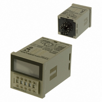
Specifications of H3CA-A
H3CAA
Z2359


Related parts for H3CA-A


H3CA-A Summary of contents
Page 1
... G: Signal ON/OFF-delay operation (2) H: Signal OFF-delay operation (2) (See note.) Solder terminal PL11 PL08 1 s 0.1 min 1 min CSM_H3CA_DS_E_2_1 Mounting Surface Flush mounting mounting/ track mounting H3CA-A H3CA-A H3CA-FA --- H3CA-8 H3CA-8 H3CA-8H H3CA-8H Back connecting socket Screw terminal P3GA-11 P3G-08 0.1 hrs hrs 1 ...
Page 2
... Influence of voltage Influence of temperature ±0.5% ±0.05 s max. Setting error Reset time H3CA-A/-FA: 0.5 s max. H3CA-8H/-8: 0.1 s max. Insulation resistance 100 MΩ min. (at 500 VDC) Dielectric strength 2,000 VAC, 50/60 Hz for 1 min (between current-carrying and non-current-carrying parts and between contact and control circuit) ...
Page 3
... Note: 1. The H3CA Series has been tested for the following: impulse voltages, noise (via noise simulator, for L loads, and for relay oscillation), and resistance to static electricity. 2. Minimum applicable load (P reference values): H3CA-A(FA), H3CA-8H: 100 VDC H3CA- VDC H3CA-FA Operation Mode Selector ...
Page 4
... Operation ■ Timing Chart H3CA-A (FA) ON-delay Operation (A Mode) Signal Start t: Set time; t-a: Time within the set time Note: The minimum signal input time is 0.05 s. Flicker Operation (B Mode) Signal Start t: Set time; t-a: Time within the set time Note: The minimum signal input time is 0.05 s. ...
Page 5
... Set time; t-a: Time within the set time t: Set time Power-ON Start/Power-OFF Reset t: Set time; t-a: Time within the set time Note: The minimum signal input time is 0.05 s. Signal ON/OFF-delay Operation 2 (H Mode) t-a t: Set time; t-a: Time within the set time H3CA 5 ...
Page 6
... Also, while a check signal is being input, the elapsed time measurement of the set time is not performed. ON-delay Operation . 2 Repeat Cycle Operation H3CA t: Set time; t-a: Time within the set time t: Set time; t-a: Time within the set time 6 ...
Page 7
... Dimensions Note: All units are in millimeters unless otherwise indicated. ■ Timers H3CA-A/-8H Panel Cutouts When mounting Horizontally connecting n units No front cover: a single unit N = (48n − 2. − 3.2 mm With front cover {48n − 2 − +0.6 −0 (N) ■ Accessories (Order Separately) Track Mounted Front Connecting Socket P2CF-11 Eleven, M3.5 × ...
Page 8
... Terminal Arrangement Mounting Holes (Bottom View) Two, 3.5 dia socket mounting holes Terminal Arrangement Mounting Holes (Bottom View) Two, 3.5 dia socket mounting holes H3CA Mounting Height of Timer with Socket 86.3 10.9 P3G-08 Mounting Height of Timer with Socket Hold-down clip 79.6 ...
Page 9
... Y92A-48B Protective Cover attached, which must be taken into consideration before using the Y92A-48B Protective Cover. When attaching the Y92A-48A to the Timer to be panel-mounted, use the Y92F-30 Mounting Adapter along with the Timer. The Protective Cover cannot be, however, used for the H3CA-FA Series. H3CA 9 ...
Page 10
... Note: 1. *C: Check: 3-4 *G: Gate: 3-5 *S: Start: 3-6 *R: Reset: 3-7 2. Conventional time-limit contacts are symbolized as However, the contacts of H3CA-A are symbolized as because timer has 8 operation modes. ■ Input Connections Signal Inputs Connect the start input contact between terminals C and F, the reset input contact between terminals C and G, the gate input contact between terminals C and E, and the check input contact between terminals C and D ...
Page 11
... Note: Except for the power supply circuitry, avoid the laying of input signal wires in parallel or in the same conduit with high-tension or power lines recommended to use shielded wires or wiring with independent metal conduits for the shortest possible distance. H3CA-8H (-) (+) H3CA-8 (-) (+) H3CA 11 ...
Page 12
... Application Examples Standard type H3CA is used for the following application examples. In the schematic diagrams, each thick the indicates the wiring necessary for selecting the desired operation mode. ON-delay Operation (A Mode) Power-ON Start/Power-OFF Reset (+) or (−) (+) or (−) Flicker Operation (B Mode) Power-ON Start/Power-OFF Reset (+) or (− ...
Page 13
... Interval Operation (E Mode) Power-ON Start/Power-OFF Reset One-shot and Flicker Operation (F Mode) Power-ON Start/Power-OFF Reset Signal Start/Signal Reset (+) or (−) (+) or (−) Signal Start/Signal Reset (+) or (−) (+) or (−) Signal OFF-delay Operation 2 (H Mode) Signal/Instantaneous Operation/Time-limit Reset (+) or (−) (+) or (−) H3CA (+) or (−) (+) or (−) (+) or (−) (+) or (−) (+) or (−) (+) or (−) 13 ...
Page 14
... A1 and A2). When connecting a DC power supply to the H3CA-8 or H3CA-8H, however, the polarity must be connected as indicated. Although there is a wide range of power connectable to the H3CA-A and H3CA-FA, be sure that there is no inductive voltage or residual voltage applied to the timer power supply terminals (2 and 10 and A2) when the power switch is turned OFF ...
Page 15
... Input terminal Circuit Isolation transformer is required. A transformer is not used in the power supplies for the H3CA-A and H3CA-FA. You can therefore receive an electrical shock by touching the input terminals when the power supply voltage is being applied. Take adequate precautions to protect against electrical shock. ...
Page 16
... Cancellation; Etc. Orders are not subject to rescheduling or cancellation unless Buyer indemnifies Omron against all related costs or expenses. 10. Force Majeure. Omron shall not be liable for any delay or failure in delivery resulting from causes beyond its control, including earthquakes, fires, floods, strikes or other labor disputes, shortage of labor or materials, accidents to machinery, acts of sabotage, riots, delay in or lack of transportation or the requirements of any government authority ...
Page 17
... OMRON ELETRÔNICA DO BRASIL LTDA • HEAD OFFICE São Paulo, SP, Brasil • 55.11.2101.6300 • www.omron.com.br OMRON ELECTRONICS MEXICO • HEAD OFFICE Apodaca, N.L. • 52.811.156.99.10 • 001.800.556.6766 • mela@omron.com Cat. No. CSM_H3CA_DS_E_2_1 OMRON ARGENTINA • SALES OFFICE Cono Sur • 54.11.4783.5300 OMRON CHILE • SALES OFFICE Santiago • ...