H3CR-A AC100-240/DC100-125 Omron, H3CR-A AC100-240/DC100-125 Datasheet - Page 16
H3CR-A AC100-240/DC100-125
Manufacturer Part Number
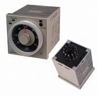
H3CR-A AC100-240/DC100-125
Description
RELAY TIMER DPDT ANALOG 120\240V
Manufacturer
Omron
Series
H3CR-Ar
Specifications of H3CR-A AC100-240/DC100-125
Mounting Type
Socket
Relay Type
Integrated
Function
Programmable (Multi-Function)
Circuit
DPDT (2 Form C)
Delay Time
0.05 Sec ~ 300 Hrs
Output Type
Mechanical Relay
Contact Rating @ Voltage
5A @ 240VAC
Voltage - Supply
100 ~ 240VAC, 100 ~ 125VDC
Termination Style
11 Pin Socketable
Timing Adjustment Method
Hand Dial
Timing Initiate Method
Input Voltage
Time Range
0.05 Sec. To 300 Hr.
Supply Voltage Ac, Min
100VAC
No. Of Timing Functions
6
Body Material
95B5375
No. Of Pins
11
Supply Voltage Ac, Max
240VAC
Load Current Rms Max
5A
Rohs Compliant
Yes
Lead Free Status / RoHS Status
Lead free / RoHS Compliant
Other names
H3CR-A AC100-240/DC100-125Q
H3CR-A-AC100-240
H3CR-A-AC100-240 DC1
H3CR-A-AC100-240 DC100-125
H3CRAAC100240DC100125
H3CRAAC100240DC100125Q
Z876
H3CR-A-AC100-240
H3CR-A-AC100-240 DC1
H3CR-A-AC100-240 DC100-125
H3CRAAC100240DC100125
H3CRAAC100240DC100125Q
Z876


Application Examples (H3CR-A)
A Mode: ON-delay
ON-delay operation (A mode) is a basic mode.
1. Power-ON Start/Power-OFF Reset
The Power-ON start/Power-OFF reset operation is a standard
operating method.
2. Signal Start/Signal Reset
The Signal start/Signal reset operation is useful for remote control of
the Timer.
Control output: NC (8 and 11)
Control output: NO (9 and 11)
Control output: NC (8 and 11)
Control output: NO (9 and 11)
Power (2 and 10)
Power indicator
Power (2 and 10)
Start (2 and 6)
Reset (2 and 7)
Externally short-circuited
Reset (2 and 7)
Power indicator
Start (2 and 6)
NC (1 and 4)
NO (1 and 3)
NC (1 and 4)
NO (1 and 3)
Start signal (remote control possible)
Reset signal
(remote control possible)
Lit
(Power continuously supplied)
Flashing
Flashing
t
t
Power
supply
Power
supply
Lit
Lit
3. Control of Integrated Time with Gate
With a gate signal, the Power-ON start operation and Signal start
operation can be controlled (the operation can be interrupted).
B/B2 Mode: Flicker
The flicker operation in the B and B2 modes can be effectively
applied to lamp or buzzer (ON and OFF) alarms or the monitoring of
an intermittent operation with a display.
1. Power-ON Start/Power-OFF Reset (in B
Control output: NC (8 and 11)
Control output: NO (9 and 11)
Control output: NC (8 and 11)
Control output: NO (9 and 11)
Signal
Mode)
Externally short-circuited
Power (2 and 10)
Power (2 and 10)
Power indicator
Power indicator
Start (2 and 6)
Gate (2 and 5)
Start (2 and 6)
Gate signal (The operation is interrupted with the
gate signal if the Timer detects an abnormal signal.)
NC (1 and 4)
NO (1 and 3)
NC (1 and 4)
NO (1 and 3)
Externally
short-circuited
t
1
Flashing
Power
supply
Power
supply
Flashing
t
2
t
1
+ t
H3CR-A
2
: set time
Lit
16
Related parts for H3CR-A AC100-240/DC100-125
Image
Part Number
Description
Manufacturer
Datasheet
Request
R

Part Number:
Description:
RELAY ANALOG SET DPDT 8PIN
Manufacturer:
Omron
Datasheet:

Part Number:
Description:
RELAY ANALOG SET DPDT 8PIN
Manufacturer:
Omron
Datasheet:

Part Number:
Description:
RELAY REPEAT CYCLE ANALOG 30HRS
Manufacturer:
Omron
Datasheet:
Part Number:
Description:
RELAY REPEAT CYCLE ANALOG 30HRS
Manufacturer:
Omron
Datasheet:

Part Number:
Description:
Timer; Repeat Cycle; 0.05s-30h; E-Mech; Ctrl-V 100-240AC; 5A@250VAC/30VDC; 8-Pin Octal
Manufacturer:
Omron Automation
Datasheet:
Part Number:
Description:
Timer; Repeat Cycle; 0.05s-30h; E-Mech; Ctrl-V 100-240AC; 5A@250VAC/30VDC; 11-PinOctal
Manufacturer:
Omron Automation
Datasheet:
Part Number:
Description:
G6S-2GLow Signal Relay
Manufacturer:
Omron Corporation
Datasheet:
Part Number:
Description:
Compact, Low-cost, SSR Switching 5 to 20 A
Manufacturer:
Omron Corporation
Datasheet:
Part Number:
Description:
Manufacturer:
Omron Corporation
Datasheet:
Part Number:
Description:
Manufacturer:
Omron Corporation
Datasheet:
Part Number:
Description:
Manufacturer:
Omron Corporation
Datasheet: