H3DE-S2 AC/DC24-230 Omron, H3DE-S2 AC/DC24-230 Datasheet - Page 24
H3DE-S2 AC/DC24-230
Manufacturer Part Number
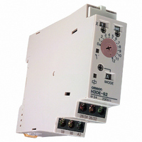
H3DE-S2 AC/DC24-230
Description
RELAY TIMER ANALOG DIN 4 MODE
Manufacturer
Omron
Series
H3DEr
Specifications of H3DE-S2 AC/DC24-230
Relay Type
Integrated
Function
Programmable (Multi-Function)
Circuit
DPDT (2 Form C)
Delay Time
0.1 Sec ~ 120 Hrs
Output Type
Mechanical Relay
Contact Rating @ Voltage
5A @ 250VAC
Voltage - Supply
24 ~ 230VAC/DC
Mounting Type
DIN Rail
Termination Style
Screw Terminal
Timing Adjustment Method
Screwdriver Slot
Timing Initiate Method
Input Voltage
Lead Free Status / RoHS Status
Contains lead / RoHS compliant by exemption
Other names
H3DE-S2 AC/DC 24-230
H3DES2ACDC24230
Z1141
H3DES2ACDC24230
Z1141


J INPUT/OUTPUT
Relationship between Input and
Power Supply Circuits
Since the input circuit and the power supply circuit are configured
independently, the input circuit can be turned on or off
irrespective of the on/off state of the power supply.
It must be noted that a voltage equivalent to the power supply
voltage is applied to the input circuit.
When connecting a relay or a transistor as an external signal
input device, pay attention to the following points to prevent
short-circuiting due to a sneak current to the transformerless
power supply.
If a relay or transistor is connected to two or more Timers, the
input terminals of those Timers must be wired properly so that
they will not be different in phase or the terminals will be
short-circuited to one another (refer to the figures below).
Note: The H3DE Series is provided with a transformerless pow-
Incorrect
Contact or transistor for external input signal
Correct
AC/DC
power
supply
Contact or transistor for external input signal
Short-circuit
current
er supply system.
Short-circuit
current
Input circuit
B1
B1
B1
H3DE
H3DE
A2
B1
B1
Power supply
circuit
A1
A2
A1
A2
H3DE
H3DE
A1
A1
A2
A1
A2
Power supply
Power supply
J INPUT WIRES
The input wires must be as short as possible. If the floating
capacity of wires exceeds 2,000 pF (approx. 17 m for cables with
120 pF/m), the operation will be affected. Pay particular attention
when using shielded cables.
J VDE CONFORMANCE
The H3DE as a built-in timer conforms to VDE 0435/P2021
provided that the following conditions are satisfied:
The output section of the H3DE is provided only with basic
isolation. To ensure reinforced isolation required by the VDE
standards, provide supplementary basic isolation on the load side
connected to the output.
The H3DE itself is designed according to the following:
•
•
The following facts are based on the above standards:
•
•
J ENVIRONMENT
When using the Timer in an area with excess electronic noise,
separate the Timer, wiring, and the equipment which generates
the input signals as far as possible from the noise sources. To
further prevent electronic interference, shield the input signal
wiring.
Organic solvents (such as paint thinner), as well as very acidic or
basic solutions can damage the outer casing of the Timer.
Do not use the Timer in places where it is exposed to dust,
corrosive gas, or direct sunlight.
When storing the Timer, make sure that the ambient temperature
and humidity are within the rated values. Leave the Timer at
room temperature for at least three hours before using the Timer
if it has been stored at an ambient temperature of - -10°C or
below.
J RELAY LIFE EXPECTANCY
Built-in relay for the H3DE: G6RN; 50,000 operations min.
(8 A at 250 VAC, resistive load at 360 operations/h.)
Overvoltage category III
Pollution degree 2
Operation parts on the front and bottom: Reinforced isola-
tionwith clearance of 5.5 mm and creepage distance of 5.5
mm at 230 VAC
Output: Basic isolation with clearance of 3 mm and creepage
distance of 3 mm at 230 VAC
Related parts for H3DE-S2 AC/DC24-230
Image
Part Number
Description
Manufacturer
Datasheet
Request
R

Part Number:
Description:
Timer, Multifunction Type, DPDT, Analog, 0.1 Second to 120 Hours, 24-230 VAC/VDC
Manufacturer:
Omron Automation
Datasheet:
Part Number:
Description:
Timer, Solid State, SPDT, Analog, 0.1 Second to 120 Hours, 24-230 VAC/VDC Supply vVol
Manufacturer:
Omron Automation
Datasheet:
Part Number:
Description:
Timer, Standard Type, SPDT, Analog, 0.1 Second to 120 Hours, 24-230 VAC/VDC
Manufacturer:
Omron Automation
Datasheet:

Part Number:
Description:
TIMER, MULTIFUNCTION
Manufacturer:
Omron
Datasheet:
Part Number:
Description:
G6S-2GLow Signal Relay
Manufacturer:
Omron Corporation
Datasheet:
Part Number:
Description:
Compact, Low-cost, SSR Switching 5 to 20 A
Manufacturer:
Omron Corporation
Datasheet:
Part Number:
Description:
Manufacturer:
Omron Corporation
Datasheet:
Part Number:
Description:
Manufacturer:
Omron Corporation
Datasheet:
Part Number:
Description:
Manufacturer:
Omron Corporation
Datasheet:
Part Number:
Description:
Manufacturer:
Omron Corporation
Datasheet:
Part Number:
Description:
Manufacturer:
Omron Corporation
Datasheet: