AQZ207V Panasonic Electric Works, AQZ207V Datasheet - Page 2
AQZ207V
Manufacturer Part Number
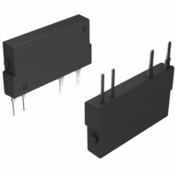
AQZ207V
Description
RELAY OPTO AC/DC 85V 1A 4-SIP
Manufacturer
Panasonic Electric Works
Series
PhotoMOS™ AQZr
Specifications of AQZ207V
Circuit
SPST-NO (1 Form A)
Output Type
AC, DC
On-state Resistance
1.1 Ohm
Load Current
1A
Voltage - Input
1.16VDC
Voltage - Load
0 ~ 85 V
Mounting Type
Through Hole
Termination Style
PC Pin
Package / Case
4-SIP
Input Type
DC
Input Voltage (max)
1.5V
Output Voltage (max)
85V
Input Current (max)
50mA
Output Current
1A
Isolation Voltage
2.5kV
Circuit Arrangement
1 Form A
Package Type
SIL
Output Device
MOSFET
Pin Count
4
Mounting
Through Hole
Operating Temp Range
-40C to 85C
Operating Temperature Classification
Industrial
Rad Hardened
No
Lead Free Status / RoHS Status
Lead free / RoHS Compliant
Available stocks
Company
Part Number
Manufacturer
Quantity
Price
Company:

Part Number:
AQZ207V
Manufacturer:
PANASONIC
Quantity:
3 600
Company:
Part Number:
AQZ207V
Manufacturer:
NAIS
Quantity:
11 200


AQZ20❍V
2) Electrical characteristics (Ambient temperature: 25°C 77°F)
3) Internal varistor characteristics
Note: When using the relay to absorb the reverse voltage during inductive load switching, make sure the load is within the inductance range given in
Note: Recommendable LED forward current I
*Turn on/off time
REFERENCE DATA
1. Load current vs. ambient temperature char-
acteristics
Allowable ambient temperature: –40°C to +85°C
618
Input
Output
Transfer
characteristics
Vibration resistance
Shock resistance
Varistor voltage
Maximum energy
Output
Input
the internal varistor characteristics data below, rather than the energy resistance range for the internal varistor. Note, the inductance range will
differ if the switching frequency is higher than the rate given for the characteristics data conditions.
3.5
3.0
2.5
2.0
1.5
1.0
0.5
0
-40
Ton
-20
Item
LED operate current
LED turn off current
LED dropout voltage
On resistance
Off state leakage current
Switching
speed
I/O capacitance
Initial I/O isolation
resistance
Maximum operating
frequency
AQZ204V
0
Ambient temperature, °C
AQZ207V
20
Item
40
–40°F to +185°F
Turn on time*
Turn off time*
AQZ202V
60
AQZ205V
8085 100
Toff
AQZ202V
Typical
Maximum
Minimum
Typical
Typical
Maximum
Typical
Maximum
Maximum
Typical
Maximum
Typical
Maximum
Typical
Maximum
Typical
Maximum
Minimum
Maximum
Minimum
Minimum
F
0.5 J
27 V
= 5 to 10 mA.
90%
10%
2. Load current vs. ambient temperature char-
acteristics in adjacent mounting
I
I
L
L
: Load current;
(max.): Maximum continuous load current
■ For Dimensions, see Page 442.
■ For Schematic and Wiring Diagrams, see Page 448.
■ For Cautions for Use, see Page 453.
Symbol AQZ202V AQZ205V AQZ207V AQZ204V
120
100
80
60
40
20
I
C
R
0
R
I
I
T
T
V
Leak
—
—
—
Fon
Foff
-40
on
off
iso
iso
on
F
= Adjacent mounting pitch
-20
2.46 ms
5.64 ms
0.22 ms
0.11 Ω
0.18 Ω
10 to 55 Hz at double amplitude of 3 mm
0
Ambient temperature, °C
AQZ205V
20
1.0 J
47 V
1.25 V (1.16 V at I
4,900 m/s
40
0.23 Ω
0.34 Ω
2.40 ms
5.65 ms
0.21 ms
60
1,000 MΩ
= 20mm
10.0 ms
1.0 mA
3.0 mA
0.4 mA
0.9 mA
1.0 cps
5.0 ms
3.0 ms
= 10mm
0.8 pF
1.5 pF
= 5mm
80 85
1.5 V
1 mA
2
{500 G}1 ms
100
1.12 ms
2.57 ms
0.10 ms
0.7 Ω
1.1 Ω
F
= 10 mA
AQZ207V
3.-(1) On resistance vs. ambient temperature
characteristics
LED current: 10 mA;
Continuous load current: 3.0 A (DC) (AQZ202V),
100 V
2.0 J
2.1 Ω
3.2 Ω
1.65 ms
3.88 ms
0.08 ms
0.5
0.4
0.3
0.2
0.1
0
-40
500 V DC
I
V
I
V
I
I
I
Within 1 s on time
I
V
I
I
V
I
I
V
I
I
V
f = 1 MHz
V
I
Duty factor = 50%
I
2 hours for 3 axes
3 times for 3 axes
F
L
L
F
L
F
F
L
F
L
F
L
F
L
= Max., V
L
L
L
L
L
L
B
= 100 mA
= 100 mA
= 10 mA
= Max.
= 100 mA
= 100 mA
= 100 mA
= 50 mA
= 0
= 10 mA
= 5 mA
= 5 mA or 10 mA
= 10 mA
= 10 V
= 10 V
= Max. DC
= 10 V
= 10 V
= 10 V
-20
= 0
Ambient temperature, °C
0
L
2.0 A (DC) (AQZ205V),
AQZ202V
AQZ205V
Remarks
= Max.
20
AQZ204V
220 V
40
4.5 J
60
8085
Related parts for AQZ207V
Image
Part Number
Description
Manufacturer
Datasheet
Request
R

Part Number:
Description:
Solid State Relays Heat sink for AQ1 solid state relay
Manufacturer:
Panasonic
Datasheet:

Part Number:
Description:
SSR 2A 264VAC 5VDC-IN ZERO-CROSS
Manufacturer:
Panasonic Electric Works
Datasheet:

Part Number:
Description:
SSR 2A 264VAC 12VDC-INPUT
Manufacturer:
Panasonic Electric Works
Datasheet:

Part Number:
Description:
RELAY SSR ZC 0.9A 600V 8 DIP
Manufacturer:
Panasonic Electric Works
Datasheet:

Part Number:
Description:
RELAY SSR 1.2A 600V 8DIP
Manufacturer:
Panasonic Electric Works
Datasheet:
Part Number:
Description:
RELAY SSR ZC 1.2A 600VAC 8DIP
Manufacturer:
Panasonic Electric Works
Datasheet:
Part Number:
Description:
RELAY SSR ZC 0.6A 600V 8 DIP
Manufacturer:
Panasonic Electric Works
Datasheet:

Part Number:
Description:
RELAY SSR ZC 0.9A 600V 8 SMD
Manufacturer:
Panasonic Electric Works
Datasheet:
Part Number:
Description:
RELAY SSR NON-ZC 0.9A 600V 8 DIP
Manufacturer:
Panasonic Electric Works
Datasheet:

Part Number:
Description:
SSR ZC 30A 75-250VAC 4-6VDC
Manufacturer:
Panasonic Electric Works
Datasheet:

Part Number:
Description:
CONN SOCKET P4 .4MM 50POS SMD
Manufacturer:
Panasonic Electric Works
Datasheet:
Part Number:
Description:
CONN SOCKET .8MM 16POS SMD
Manufacturer:
Panasonic Electric Works
Datasheet:
Part Number:
Description:
CONN HEADER .8MM 16POS SMD
Manufacturer:
Panasonic Electric Works
Datasheet:
Part Number:
Description:
CONN SOCKET .8MM 20POS SMD
Manufacturer:
Panasonic Electric Works
Datasheet:
Part Number:
Description:
CONN SOCKET .8MM 20POS SMD
Manufacturer:
Panasonic Electric Works
Datasheet: