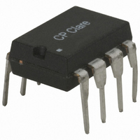
LBB120 Clare, LBB120 Datasheet - Page 2

LBB120
Manufacturer Part Number
LBB120
Description
RELAY OPTOMOS 170MA DP-NC 8-DIP
Manufacturer
Clare
Series
LBB, OptoMOS®r
Datasheet
1.LBB120.pdf
(7 pages)
Specifications of LBB120
Circuit
DPST (2 Form B)
Output Type
AC, DC
On-state Resistance
20 Ohm
Load Current
170mA
Voltage - Input
1.2VDC
Voltage - Load
0 ~ 250 V
Mounting Type
Through Hole
Termination Style
PC Pin
Package / Case
8-DIP (0.300", 7.62mm)
Load Voltage Rating
250 V
Load Current Rating
170 mA
Relay Type
Dual Pole
Lead Free Status / RoHS Status
Lead free / RoHS Compliant
Available stocks
Company
Part Number
Manufacturer
Quantity
Price
Part Number:
LBB120
Manufacturer:
CLARE
Quantity:
20 000
Company:
Part Number:
LBB120H
Manufacturer:
MOTOROLA
Quantity:
1 940
Company:
Part Number:
LBB120HS
Manufacturer:
CPClare
Quantity:
103
Part Number:
LBB120HS
Manufacturer:
CLARE
Quantity:
20 000
Absolute Maximum Ratings @ 25ºC
Electrical Characteristics @ 25ºC
2
Parameter
Blocking Voltage
Reverse Input Voltage
Input Control Current
Input Power Dissipation
Total Power Dissipation
Isolation Voltage, Input to Output
Operational Temperature
Storage Temperature
Parameter
Output Characteristics
Load Current
On-Resistance, AC/DC Configuration
Off-State Leakage Current
Switching Speeds
Output Capacitance
Input Characteristics
Input Control Current
Input Dropout Current
Input Voltage Drop
Reverse Input Current
Common Characteristics
Input to Output Capacitance
Peak (10ms)
1
2
1
2
Turn-On
Turn-Off
Continuous, AC/DC Configuration
Peak
Derate Linearly 1.33 mW / ºC
Derate Linearly 6.67 mW / ºC
If both poles operate simultaneously, then the load current must be derated so as not to exceed the package power dissipation value.
Measurement taken within 1 second of on-time.
2
1
1
2
-40 to +125
-40 to +85
Ratings
3750
250
150
800
50
5
1
Units
mW
mW
V
mA
V
°C
°C
V
A
rms
I
V
P
F
Conditions
L
=5mA, V
=50V, f=1MHz
I
V
I
L
L
t=10ms
I
www.clare.com
=120mA
L
=170mA
V
F
=250V
=5mA
R
=5V
-
-
-
L
=10V
P
Absolute Maximum Ratings are stress ratings. Stresses in
excess of these ratings can cause permanent damage to
the device. Functional operation of the device at conditions
beyond those indicated in the operational sections of this
data sheet is not implied.
Symbol
C
I
R
I
LEAK
C
LPK
t
t
V
OUT
I
I
I
I
ON
on
off
R
I/O
L
F
F
F
Min
0.4
0.9
-
-
-
-
-
-
-
-
-
-
Typ
0.7
1.2
16
50
3
-
-
-
-
-
-
-
Max
170
400
1.4
20
10
1
5
5
5
-
-
-
Units
LBB120
mA
mA
mA
μA
ms
μA
pF
pF
Ω
V
R07


