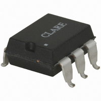
LCB110S Clare, LCB110S Datasheet - Page 2

LCB110S
Manufacturer Part Number
LCB110S
Description
RELAY OPTOMOS 120MA SP-NC 6-SMD
Manufacturer
Clare
Series
LCB, OptoMOS®r
Specifications of LCB110S
Circuit
SPST-NC (1 Form B)
Output Type
AC, DC
On-state Resistance
35 Ohm
Load Current
120mA
Voltage - Input
1.2VDC
Voltage - Load
0 ~ 350 V
Mounting Type
Surface Mount
Termination Style
Gull Wing
Package / Case
6-SMD (300 mil)
Load Voltage Rating
350 V
Load Current Rating
120 mA
Mounting Style
SMD/SMT
Relay Type
Single Pole
Load Voltage Max
350V
On State Resistance Max
35ohm
Contact Configuration
SPST-NC
Isolation Voltage
3750Vrms
Forward Current If
5mA
Relay Terminals
SMD
Rohs Compliant
Yes
Lead Free Status / RoHS Status
Lead free / RoHS Compliant
Available stocks
Company
Part Number
Manufacturer
Quantity
Price
Company:
Part Number:
LCB110S
Manufacturer:
Clare
Quantity:
5 510
Company:
Part Number:
LCB110S
Manufacturer:
CYPRESS
Quantity:
5 510
Company:
Part Number:
LCB110STR
Manufacturer:
SPT
Quantity:
120
Part Number:
LCB110STR
Manufacturer:
CPCLARE
Quantity:
20 000
LCB110
Absolute Maximum Ratings (@ 25˚ C)
2
Electrical Characteristics
Input Power Dissipation
Input Control Current
Reverse Input Voltage
Total Power Dissipation
Isolation Voltage
Operational Temperature
Storage Temperature
Soldering Temperature
Parameter
1
2
Parameter
Input to Output Isolation
Output Characteristics @ 25°C
Load Voltage (Peak)
Load Current (Continuous)
Peak Load Current
On-Resistance
Off-State Leakage Current
Switching Speeds
Output Capacitance
Input Characteristics @ 25°C
Input Control Current
Input Dropout Current
Input Voltage Drop
Reverse Input Voltage
Reverse Input Current
Input to Output Capacitance
Derate Linearly 1.33 mw/˚C
Derate Linearly 6.67 mw/˚C
Peak (10ms)
Input to Output
DIP Package
Surface Mount Package
(10 Seconds Max.)
AC/DC Configuration
DC Configuration
AC/DC Configuration
DC Configuration
Turn-On
Turn-Off
3750
Min
-40
-40
-
-
-
-
-
-
-
Typ Max Units
-
-
-
-
-
-
-
-
-
-
I
I
F
F
Conditions
=5mA, V
=5mA, V
50V; f=1MHz
I
I
I
V
L
L
L
+125
+260
+220
150
800
I
=120mA
=200mA
=120mA
+85
V
L
F
10ms
50
=35OV
=5mA
1
5
-
R
=5V
-
-
-
-
-
-
-
1
2
L
L
=10V
=10V
V
mW
mW
mA
°C
°C
°C
°C
RMS
A
V
www.clare.com
Symbol
I
C
T
R
R
T
C
V
LEAK
V
V
V
I
I
I
OUT
I
OFF
I
I
ON
ON
ON
I/O
I/O
L
L
L
R
F
F
L
R
F
Absolute Maximum Ratings are stress ratings. Stresses in
excess of these ratings can cause permanent damage to
the device. Functional operation of the device at these or
any other conditions beyond those indicated in the opera-
tional sections of this data sheet is not implied. Exposure of
the device to the absolute maximum ratings for an extend-
ed period may degrade the device and effect its reliability.
3750
Min
0.4
0.9
5
-
-
-
-
-
-
-
-
-
-
-
-
-
Typ
0.7
1.2
23
25
7
3
-
-
-
-
-
-
-
-
-
-
-
Max
350
120
200
350
1.4
35
10
50
10
1
3
3
5
-
-
-
-
Units
V
mA
mA
mA
mA
mA
ms
ms
µA
pF
µA
pF
RMS
Ω
Ω
V
V
V
Rev. 6.0


