LBB110 Clare, LBB110 Datasheet
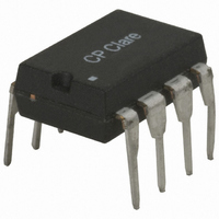
RELAY OPTO 2 CHANNEL NC/NC 8-DIP

LBB110

Manufacturer Part Number
LBB110
Description
RELAY OPTO 2 CHANNEL NC/NC 8-DIP
Manufacturer
Clare
Series
LBB, OptoMOS®r
Datasheet

Specifications of LBB110

Circuit
DPST (2 Form B)
Output Type
AC, DC
On-state Resistance
35 Ohm
Load Current
120mA
Voltage - Input
1.2VDC
Voltage - Load
0 ~ 350 V
Mounting Type
Through Hole
Termination Style
PC Pin
Package / Case
8-DIP (0.300", 7.62mm)
Input Type
DC
Input Voltage (max)
1.4V
Output Voltage (max)
350V
Input Current (max)
50mA
Output Current
120mA
Isolation Voltage
3750(RMS)V
Circuit Arrangement
2 Form B
Package Type
PDIP
Output Device
MOSFET
Pin Count
8
Mounting
Through Hole
Operating Temp Range
-40C to 85C
Operating Temperature Classification
Industrial
Rad Hardened
No
Load Voltage Rating
350 V
Load Current Rating
120 mA
Mounting Style
SMD/SMT
Relay Type
Dual Pole
Load Voltage Max
350V
On State Resistance Max
35ohm
Contact Configuration
DPST-NC
Forward Current If
50mA
Relay Terminals
Through Hole
Rohs Compliant
No
Lead Free Status / RoHS Status
Lead free / RoHS Compliant
Other names
CLA174

Available stocks

Company
Part Number
Manufacturer
Quantity
Price
Part Number:
LBB110
Manufacturer:
CLARE
Quantity:
4 356
Part Number:
LBB110
Manufacturer:
CPClARE
Quantity:
5 510
Part Number:
LBB110
Manufacturer:
CLARE
Quantity:
20 000
Part Number:
LBB110E
Quantity:
2 000
Part Number:
LBB110E
Manufacturer:
NEC
Quantity:
2 000
Part Number:
LBB110ES
Manufacturer:
VISHAY
Quantity:
40 000
Applications
DS-LBB110-R07
Features
Blocking Voltage
Load Current
Max R
Parameter
Telecommunications
Instrumentation
Medical Equipment-Patient/Equipment Isolation
Security
Aerospace
Industrial Controls
Pb
3750V
Small 8-Pin Package
Low Drive Power Requirements (TTL/CMOS
Compatible)
High Reliability
Arc-Free With No Snubbing Circuits
FCC Compatible
VDE Compatible
No EMI/RFI Generation
Machine Insertable, Wave Solderable
Surface Mount, Tape & Reel Version Available
Telecom Switching
Tip/Ring Circuits
Modem Switching (Laptop, Notebook, Pocket Size)
Hook Switch
Dial Pulsing
Ground Start
Ringing Injection
Multiplexers
Data Acquisition
Electronic Switching
I/O Subsystems
Meters (Watt-Hour, Water, Gas)
ON
rms
2002/95/EC
Input/Output Isolation
RoHS
e
3
Ratings
350
120
35
Units
mA
V
Ω
www.clare.com
P
Description
LBB110 is a dual normally closed (1-Form-B) solid
state relay that has two independently controlled,
optically coupled MOSFET switches. The efficient
MOSFET switches and photovoltaic die use Clare’s
patented OptoMOS architecture to provide 3750
V
outputs are controlled by highly efficient GaAIAs
infrared LEDs.
Dual single-pole OptoMOS relays provide a more
compact design solution than discrete single-pole
relays in a variety of applications by incorporating
both relays in a single 8-pin package.
Approvals
Ordering Information
Pin Configuration
Part #
LBB110
LBB110P
LBB110PTR
LBB110S
LBB110STR
rms
TUV Certificate B 09 07 49410 004
UL Recognized Component: File E76270
CSA Certified Component: Certificate 1175739
EN/IEC 60950-1 Certified Component:
of input to output isolation. The optically coupled
Dual Single-Pole, Normally Closed
+ Control - Switch #1
– Control - Switch #1
+ Control - Switch #2
– Control - Switch #2
Switching Characteristics of
Form-B
I
I
F
LOAD
Normally Closed Devices
Description
8-Pin DIP (50/Tube)
8-Pin Flatpack (50/Tube)
8-Pin Flatpack (1000/Reel)
8-Pin Surface Mount (50/Tube)
8-Pin Surface Mount (1000/Reel)
1
2
3
4
10%
t
off
OptoMOS
8
7
6
5
Load - Switch #1
Load - Switch #1
Load - Switch #2
Load - Switch #2
90%
t
on
LBB110
®
Relay
1

Related parts for LBB110

LBB110 Summary of contents

Page 1

... Industrial Controls e Pb RoHS 3 2002/95/EC DS-LBB110-R07 Dual Single-Pole, Normally Closed Description Units LBB110 is a dual normally closed (1-Form-B) solid 350 V P state relay that has two independently controlled, 120 mA optically coupled MOSFET switches. The efficient Ω 35 MOSFET switches and photovoltaic die use Clare’s ...

Page 2

... A 150 mW 800 mW 3750 V rms °C °C Conditions Symbol - I L t=10ms I LPK I =120mA =350V LEAK =5mA, V =10V off V =50V, f=1MHz C L OUT I =120mA =5mA = I/O www.clare.com LBB110 Min Typ Max Units - - 120 350 Ω μ 0.4 0 0.9 1.2 1.4 V μ R07 ...

Page 3

... P Typical Turn-On vs. LED Forward Current (I =120mA ) L DC 0.30 0.25 0.20 0.15 0.10 0.05 0 120 LED Forward Current (mA) Typical Turn-Off vs. Temperature (I =120mA ) L DC 2.0 1.8 I =5mA F 1.6 I =10mA F 1.4 1.2 1.0 0.8 0.6 0.4 0 100 -40 - Temperature (ºC) LBB110 31.5 432 100 3 ...

Page 4

... Temperature (ºC) Energy Rating Curve 1.0 0.9 0.8 0.7 0.6 0.5 0.4 0.3 0.2 0.1 0 100 10μs 100μs 1ms 10ms 100ms 1s 10s Time www.clare.com LBB110 Typical On-Resistance vs. Temperature (I =120mA ) Dual Pole 45 Single Pole 40 Instantaneous -40 - 100 Temperature (ºC) Typical Blocking Voltage vs ...

Page 5

... This product carries a Moisture Sensitivity Level (MSL) rating as shown below, and should be handled according to the requirements of the latest version of the joint industry standard IPC/JEDEC J-STD-033. Device LBB110 / LBB110S / LBB110P ESD Sensitivity This product is ESD Sensitive, and should be handled according to the industry standard JESD-625. ...

Page 6

... LBB110 PCB Hole Pattern 8-0.800 DIA. 2.540 ± 0.127 (8-0.031 DIA.) (0.100 ± 0.005) 6.350 ± 0.127 (0.250 ± 0.005) 7.620 ± ...

Page 7

... LBB110P Tape & Reel 330.2 DIA. (13.00 DIA.) Top Cover Tape Thickness 0.102 MAX. (0.004 MAX.) Embossed Carrier Embossment LBB110S Tape & Reel 330.2 DIA. (13.00 DIA.) Top Cover Tape Thickness 0.102 MAX. (0.004 MAX.) Embossed Carrier Embossment For additional information please visit our website at: www.clare.com Clare, Inc. makes no representations or warranties with respect to the accuracy or completeness of the contents of this publication and reserves the right to make changes to specifications and product descriptions at any time without notice. Neither circuit patent licenses nor indemnity are expressed or implied. Except as set forth in Clare’ ...

Related keywords