LCB110 Clare, LCB110 Datasheet
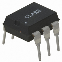
RELAY OPTO 12OMA SPST-NC 6-DIP

LCB110

Manufacturer Part Number
LCB110
Description
RELAY OPTO 12OMA SPST-NC 6-DIP
Manufacturer
Clare
Series
LCB, OptoMOS®r
Datasheet

Specifications of LCB110

Circuit
SPST-NC (1 Form B)
Output Type
AC, DC
On-state Resistance
35 Ohm
Load Current
120mA
Voltage - Input
1.2VDC
Voltage - Load
0 ~ 350 V
Mounting Type
Through Hole
Termination Style
PC Pin
Package / Case
6-DIP (0.300", 7.62mm)
Load Voltage Rating
350 V
Load Current Rating
120 mA
Mounting Style
SMD/SMT
Relay Type
Single Pole
Lead Free Status / RoHS Status
Lead free / RoHS Compliant
Other names
CLA105

Available stocks

Company
Part Number
Manufacturer
Quantity
Price
Part Number:
LCB110
Quantity:
407
Part Number:
LCB110
Manufacturer:
Clare
Quantity:
5 510
Part Number:
LCB110
Manufacturer:
CLARE
Quantity:
20 000
Company:
Part Number:
LCB110
Quantity:
3 120
Company:
Part Number:
LCB110CP
Quantity:
44
Part Number:
LCB110E
Manufacturer:
Clare
Quantity:
5 510
Part Number:
LCB110E
Manufacturer:
MAXIM
Quantity:
5 510
Part Number:
LCB110ES
Manufacturer:
CPCLARE
Quantity:
2 000
Part Number:
LCB110STR
Manufacturer:
CPCLARE
Quantity:
20 000
DS-LCB110-R07
Features
Applications
Parameter
Blocking Voltage
Load Current
Max On-resistance
Telecommunications
Size)
Instrumentation
Medical Equipment-Patient/Equipment Isolation
Security
Aerospace
Industrial Controls
Small 6-Pin Package
Low Drive Power Requirements (TTL/CMOS
Compatible)
Arc-Free With No Snubbing Circuits
3750V
FCC Compatible
VDE Compatible
No EMI/RFI Generation
Machine Insertable, Wave Solderable
Surface Mount Tape & Reel Version Available
Pb
Telecom Switching
Tip/Ring Circuits
Modem Switching (Laptop, Notebook, Pocket
Hook Switch
Dial Pulsing
Ground Start
Ringing Injection
Multiplexers
Data Acquisition
Electronic Switching
I/O Subsystems
Meters (Watt-Hour, Water, Gas)
rms
2002/95/EC
Input/Output Isolation
RoHS
e
Ratings
3
350
120
35
Units
mA
V
Ω
P
www.clare.com
Pin Configuration
Approvals
* For other packaging options consult factory.
Description
The LCB110 is a 1-Form-B (normally closed) relay
which uses optically coupled MOSFET technology
to provide 3750V
efficient MOSFET switches and photovoltaic die use
Clare’s patented OptoMOS
efficient GaAIAs infrared LED controls the optically
coupled output. The LCB110 has low on-resistance
and is well suited for most applications requiring a
normally closed relay.
Ordering Information
+ Control
– Control
Part #
LCB110
LCB110S
LCB110STR
UL Recognized Component: File # E76270
CSA Certified Component: Certificate # 1175739
EN/IEC 60950-1 Compliant
N/C
AC/DC Configuration
1
2
3
CONTROL
I
Single Pole OptoMOS
LOAD
Normally Closed (Form B) Devices
Switching Characteristics of
Description
6-Pin DIP (50/Tube)
6-Pin Surface Mount (50/Tube)
6-Pin Surface Mount (1000/Reel)
rms
6
5
4
Load
Do Not Use
Load
of input to output isolation. The
+
10%
®
T
+ Control
– Control
OFF
architecture. A highly
N/C
DC Only Configuration
1
2
3
+
90%
T
ON
LCB110
®
6
5
4
Relay
+ Load
– Load
1

Related parts for LCB110

LCB110 Summary of contents

Page 1

... RoHS 2002/95/EC DS-LCB110-R07 Single Pole OptoMOS Description Units V The LCB110 is a 1-Form-B (normally closed) relay P mA which uses optically coupled MOSFET technology Ω to provide 3750V efficient MOSFET switches and photovoltaic die use Clare’s patented OptoMOS efficient GaAIAs infrared LED controls the optically coupled output ...

Page 2

... LCB110 Absolute Maximum Ratings Parameter Ratings Blocking Voltage Reverse Input Voltage Input Control Current Peak (10ms) 1 Input Power Dissipation 2 Total Power Dissipation Isolation voltage Input to Output Operational Temperature -40 to +85 Storage Temperature -40 to +125 1 Derate Linearly 3. ºC 1 Derate Linearly 6. ºC Electrical absolute maximum ratings are at 25°C ...

Page 3

... Temperature (ºC) www.clare.com LCB110 Typical Blocking Voltage Distribution ) (N=50, T =25ºC, I =5mA 24.2 370 375 380 385 Blocking Voltage (V LCB110 Typical Turn-On Time (N=50, T =25ºC, I =120mA ) 0.70 0.18 0.25 0.32 0.39 Turn-On (ms) LCB110 Typical Leakage vs. Temperature (Measured Across Pins 4&6) ...

Page 4

... LED Forward Current (mA) LCB110 Typical On-Resistance vs. Temperature (I =100mA Instantaneous -40 - 100 Temperature (ºC) LCB110 Typical Load Current vs. Load Voltage (T =25ºC) A 150 100 50 0 -50 -100 -150 - Load Voltage (V) www.clare.com LCB110 Typical Turn-Off vs. LED Forward Current (I =120mA ) L DC 0.7 0.6 0.5 0.4 ...

Page 5

... TYP (0.010 TYP) 0.635 ± 0.127 (0.025 ± 0.005) 7.620 ± 0.254 0.254 ± 0.0127 (0.300 ± 0.010) (0.010 ± 0.0005) www.clare.com LCB110 e Pb RoHS 3 2002/95/EC PC Board Pattern 6 - 0.800 DIA. 2.540 ± 0.127 (6 - 0.031 DIA.) (0.100 ± 0.005) 7.620 ± ...

Page 6

... User Direction of Feed NOTE: Tape dimensions not shown comply with JEDEC Standard EIA-481-2 LCB110 W = 16.00 MAX (0.63 MAX 10.10 0 (0.400 10.10 0 (0.400) Dimensions mm (inches) Specification: DS-LCB110-R07 ©Copyright 2008, Clare, Inc. OptoMOS® registered trademark of Clare, Inc. All rights reserved. Printed in USA. 7/23/08 ...

Related keywords