DSP2A-PSL2 Panasonic Electric Works, DSP2A-PSL2 Datasheet - Page 3
DSP2A-PSL2
Manufacturer Part Number
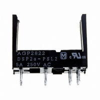
DSP2A-PSL2
Description
SOCKET PC MNT FOR DSP2A-L2 RELAY
Manufacturer
Panasonic Electric Works
Series
DSPr
Type
Socketr
Specifications of DSP2A-PSL2
Number Of Positions
8
Mounting Type
Through Hole
Termination Style
PC Pin
Current Rating
5 A
Height
17 mm
Length
23 mm
Mounting
PCB
Number Of Contacts
8
Resistance, Insulation
1000 Megohms (Between Terminals)
Termination
PCB Pins
Voltage, Breakdown
3000 V (RMS)
Width
11 mm
For Use With/related Products
DSP2A-L2 and DSP1-L2 Relays
For Use With
DSP1-L2-DC24V-F - RELAY PWR DPST LATCH 5A 24VDC PC255-2744 - RELAY PWR DPST LATCH 5A 12VDC PCDSP1-L2-DC9V-F - RELAY PWR DPST LATCH 5A 9VDC PCBDSP1-L2-DC6V-F - RELAY PWR DPST LATCH 5A 6VDC PCB255-2745 - RELAY PWR DPST LATCH 5A 5VDC PCBDSP1-L2-DC3V-F - RELAY PWR DPST LATCH 5A 3VDC PCBDSP2A-L2-DC9V - RELAY MINI PWR 2-LATCH 9VDC PCBDSP2A-L2-DC3V - RELAY MINI PWR 2-LATCH 3VDC PCB255-1626 - RELAY LATCHING 5A 5VDC PCB255-1625 - RELAY LATCHING 5A 24VDC PCB255-1624 - RELAY LATCHING 5A 12VDC PCB
Lead Free Status / RoHS Status
Lead free / RoHS Compliant
Other names
255-1061


DSP
2a type (DSP2a)
REFERENCE DATA
1. Max. switching capacity
3.-(1) Coil temperature rise (1a type)
Sample: DSP1a-DC12V, 5 pcs.
4.-(1) Operate & release time
(without diode, 1a type)
Sample: DSP1a-DC12V, 5 pcs.
0.1
60
50
40
30
20
10
10
1
0
7
6
5
4
3
2
1
0
10
DC resistive
load (1a)
DC resistive load
(1a1b,2a)
80
80
Coil applied voltage, %V
Coil applied voltage, %V
Contact voltage, V
Single side stable
1 coil latching
AC resistive
.031
0.8
(1a1b,2a)
100
100
100
load
7.62
.300
Operate time
Release time
AC resistive
20.2
.795
.039
1.0
load (1a)
10.16
.400
120
120
.283
8A
0A
Max.
x
Min.
Max.
x
Min.
7.2
1000
0.8
.031
0.3
.012
10.0
.394
1.21
.048
All Rights Reserved © COPYRIGHT Matsushita Electric Works, Ltd.
.138
10.5
.413
3.5
2 coil latching
.031
0.8
2.-(1) Life curve (1a1b type)
3.-(2) Coil temperature rise (1a1b type)
Sample: DSP1-DC12V, 5 pcs.
4.-(2) Operate & release time
(without diode, 1a1b type)
Sample: DSP1-DC12V, 5 pcs.
7.62
.300
100
10
60
50
40
30
20
10
0
20.2
.795
9
8
7
6
5
4
3
2
1
0
.039
0
1.0
265 V·130 V AC
7.62
.300
General tolerance: ±0.3
cosϕ = 0.4
.283
1
7.2
80
80
Release time
2.54
.100
2
0.8
.031
10.0
.394
0.3
.012
1.21
.048
Coil applied voltage, %V
Coil applied voltage, %V
Switching capacity, A
.138
10.5
.413
3.5
3
265 V·130 V AC cosϕ = 1
Operate time
100
100
.039
4
1.0
7.62
.300
11.0
.433
110
5
Max.
x
Min.
Max.
x
Min.
±.012
0.3
.012
120
6
5A
0A
7
(Deenergized condition)
2.54 × 3
.100 × 3
6-1.2 dia.
6-.047 dia.
Single side stable
Single side stable
9
8
PC board pattern (Copper-side view)
12
2.-(2) Life curve (1a1b type)
3.-(3) Coil temperature rise (2a type)
Sample: DSP2a-DC12V, 5 pcs.
4.-(3) Operate & release time
(without diode, 2a type)
Sample: DSP2a-DC12V, 5 pcs.)
5
2.54 × 3
.100 × 3
Schematic (Bottom view)
100
50
10
16
2.54 × 4
.100 × 4
60
50
40
30
20
10
–
+
1
0
9
8
7
6
5
4
3
2
1
0
30 V DC L/R = 7 ms
80
80
2.54 × 3
.100 × 3
Coil applied voltage, %V
0.5
Coil applied voltage, %V
8-1.2 dia.
8-.047 dia.
Switching capacity, A
Release time
Operate time
Tolerance: ±0.1
2 coil latching
(Reset condition)
100
1
100
9
8
2 coil latching
2.54 × 3
.100 × 3
12
30 V DC resistive
5
2.54 × 3
.100 × 3
15
–
+
2
5
120
120
16
mm
Max.
Min.
Max.
Min.
5A
0A
x
x
–
+
1
±.004
10
2.54
.100
inch
Related parts for DSP2A-PSL2
Image
Part Number
Description
Manufacturer
Datasheet
Request
R

Part Number:
Description:
RELAY MINI DPST 5A 5VDC PC MNT
Manufacturer:
Panasonic Electric Works
Datasheet:
Part Number:
Description:
RELAY MINI DPST 5A 12VDC PC MNT
Manufacturer:
Panasonic Electric Works
Datasheet:
Part Number:
Description:
RELAY MINI DPST 5A 24VDC PC MNT
Manufacturer:
Panasonic Electric Works
Datasheet:

Part Number:
Description:
RELAY LATCHING 5A 12VDC PCB
Manufacturer:
Panasonic Electric Works
Datasheet:

Part Number:
Description:
SOCKET PC MNT FOR DSP2A RELAYS
Manufacturer:
Panasonic Electric Works
Datasheet:

Part Number:
Description:
RELAY MINI POWER 12VDC PCB
Manufacturer:
Panasonic Electric Works
Datasheet:
Part Number:
Description:
RELAY MINI POWER 12VDC PCB
Manufacturer:
Panasonic Electric Works
Datasheet:
Part Number:
Description:
RELAY MINI POWER 24VDC PCB
Manufacturer:
Panasonic Electric Works
Datasheet:
Part Number:
Description:
RELAY MINI POWER 3VDC PCB
Manufacturer:
Panasonic Electric Works
Datasheet:
Part Number:
Description:
RELAY MINI POWER 5VDC PCB
Manufacturer:
Panasonic Electric Works
Datasheet:

Part Number:
Description:
CONN SOCKET P4 .4MM 50POS SMD
Manufacturer:
Panasonic Electric Works
Datasheet:
Part Number:
Description:
CONN SOCKET .8MM 16POS SMD
Manufacturer:
Panasonic Electric Works
Datasheet:
Part Number:
Description:
CONN HEADER .8MM 16POS SMD
Manufacturer:
Panasonic Electric Works
Datasheet:
Part Number:
Description:
CONN SOCKET .8MM 20POS SMD
Manufacturer:
Panasonic Electric Works
Datasheet:
Part Number:
Description:
CONN SOCKET .8MM 20POS SMD
Manufacturer:
Panasonic Electric Works
Datasheet: