DSP
SPECIFICATIONS
Contact
Coil (polarized) (at 20°C 68°F)
Note: All specifications are based on the condition of 25°C 77°F, 50% R.H. unless
otherwise specified.
#1 This value can change due to the switching frequency, environmental conditions,
Remarks
* Specifications will vary with foreign standards certification ratings.
*
*
*
*
*
*
*
TYPICAL APPLICATIONS
Office and industrial electronic devices
• Terminal devices of information
processing equipment, such as printer,
data recorder.
• Office equipment (copier, facsimile)
• Measuring instruments
• NC machines, temperature controllers
and programmable logic controllers.
Arrangement
Contact material
Initial contact resistance, max.
(By voltage drop 6 V DC 1A)
Nominal switching capacity
Rating
(resistive)
Expected
life (min.
operations)
Minimum operating
power
Nominal operating
power
1
2
3
4
5
6
7
Measurement at same location as “Initial breakdown voltage” section
Detection current: 10mA
Excluding contact bounce time
Half-wave pulse of sine wave: 11ms; detection time: 10µs
Half-wave pulse of sine wave: 6ms
Detection time: 10µs
Refer to 6. Conditions for operation, transport and storage mentioned in
AMBIENT ENVIRONMENT
and desired reliability level, therefore it is recommended to check this with the
actual load.
DSP1a
Max. switching power
Max. switching voltage
Max. switching current
Min. switching capacity
Mechanical
(at 180 cpm)
Electrical
Single side stable
2 coil latching
Single side stable
2 coil latching
DSP1
(at 20 ° C
#1
mm
2,000 VA
8A 250
RELAY IN DS RELAY SERIES
150 W
5A 30
VDC
VAC
inch
Gold flash over silver alloy
8 A
1a
68 °
20.2
.795
8 A MINIATURE POWER
250 V AC, 30 V DC
All Rights Reserved © COPYRIGHT Matsushita Electric Works, Ltd.
10 mA, 5 V DC
F)
DSP2a
ORDERING INFORMATION
(Notes) 1. Standard packing–Carton: 50 pcs.; Case: 500 pcs.
30 mΩ
Contact arrangement
5×10
1a1b
10
192 mW
192 mW
300 mW
300 mW
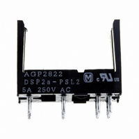
5A 250 VAC
5A 30 VDC
5
1,250 VA
7
1: 1a1b
1a: 1a
2a: 2a
150 W
Ex. DSP
5 A
2. 1 coil latching type available.
11.0
.433
UL/CSA, VDE approved type is standard.
10.5
.413
2a
FEATURES
• Power types added to DS relay series
• High switching capacity: 1a: 8 A 250 V AC /
• High sensitivity: 190 mW pick-up power
• High contact welding resistance
• Latching types available
• High breakdown voltage 3,000 Vrms between contacts and coil
• Sealed types are standard
Operating function
1
1,000 Vrms between open contacts Meeting FCC Part 68
Nil: Single side
L2: 2 coil
stable
latching
Characteristics
Max. operating speed
Initial insulation resistance*
Initial
breakdown
voltage*
Surge voltage between contacts and
coil
Set time*
Reset time*
Operate time*
Release time(without diode)*
(at nominal voltage)
Temperature rise
Soldering temperature
Shock
resistance
Vibration
resistance
Conditions for operation, transport
and storage*
(Not freezing and condensing at low
temperature)
Unit weight
2
L
3
Coil voltage
DC: 3, 5, 6,
9, 12, 24 V
(at nominal voltage)
3
7
(at nominal voltage)
Between open contacts
Between contact sets
Between contacts and
coil
Functional*
Destructive*
Functional*
Destructive
3
(at nominal voltage)
Nil: Standard
R: Reverse
DC12V
Polarity
polarity
1a1b, 2a: 5 A 250 V AC
4
6
polarity
5
1
RELAYS
3
• RoHS Directive conforming type (AgSnO
• RoHS Directive non-conforming type (AgCdO type)
F: 1a1b
Nil: 1a, 2a
Nil: 1a1b
DSP
117.6 m/s
205.8 m/s
at double amplitude of 3.5 mm
–40°C to +65°C
at double amplitude of 2 mm
Min. 1,000 MΩ at 500 V DC
Max. 10 ms (Approx. 5 ms)
Max. 10 ms (Approx. 4 ms)
Max. 10 ms (Approx. 5 ms)
R
Max. 5 ms (Approx. 4 ms)
250°C (10 s) 300°C (5 s),
Max. 55°C (1a, 2a types)
Environmental support
Max. 40°C (1a1b type)
2,000 Vrms (1a1b, 2a)
Min. 980 m/s
30 cps. at rated load
Min. 196 m/s
Approx. 4.3 g
Min. 5,000 V
1,000 Vrms
3,000 Vrms
350°C (3 s)
2
2
{12 G}, 10 to 55 Hz
{21 G}, 10 to 55 Hz
F
– 40°F 149°F
2
2
{100 G}
.15 oz
{20 G}
2
type)