G6Y-1 DC4.5 Omron, G6Y-1 DC4.5 Datasheet - Page 4
G6Y-1 DC4.5
Manufacturer Part Number
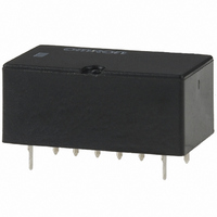
G6Y-1 DC4.5
Description
RELAY HI-FREQ SPDT 4.5VDC PCB
Manufacturer
Omron
Series
G6Yr
Datasheet
1.G6Y-1_DC5.pdf
(6 pages)
Specifications of G6Y-1 DC4.5
Relay Type
RF
Circuit
SPDT (1 Form C)
Contact Rating @ Voltage
0.01A @ 30VAC/DC
Coil Type
Standard
Coil Current
44.4mA
Coil Voltage
4.5VDC
Control On Voltage (max)
3.38 VDC
Control Off Voltage (min)
0.45 VDC
Mounting Type
Through Hole
Termination Style
PC Pin
Lead Free Status / RoHS Status
Lead free / RoHS Compliant
Other names
G6Y-1-DC4.5
G6Y1DC4.5
G6Y1DC45
G6Y1DC4.5
G6Y1DC45


Precautions
■ Correct Use
Long-term Continuously ON Contacts
Using the Relay in a circuit where the Relay will be ON continuously
for long periods (without switching) can lead to unstable contacts
because the heat generated by the coil itself will affect the insulation,
causing a film to develop on the contact surfaces. Be sure to use a
fail-safe circuit design that provides protection against contact failure
or coil burnout.
Seal integrity during cleaning will last 1 minute at 70°C. Complete
cleaning within these conditions.
Micro Strip Line Design
• It is advantageous to use the Micro Strip Line in high–frequency
• The characteristic impedance of the lines Z
W: Line width
ε
H: Dielectric base thickness
The copper foil thickness must be less than H.
• The following graph shows this relationship.
338
Z
Ground pattern
transmission circuits because a low-loss transmission can be con-
structed with this method. By etching the dielectric base which has
copper foil attached to both sides, the Micro Strip Line will have a
concentrated electric field between the lines and ground as shown
in the following diagram.
kind of base (dielectric constant), the base’s thickness, and the
width of the lines, as expressed in the following equation.
r: Effective dielectric constant
O
=
Lines with impedance Z
ε
r
W
H
High Frequency Relay
Dielectric base
(dielectric constant: ε
1+
377
πW
2H
Dielectric constant (ε
1+In
Micro Strip (w/h)
r
)
πW
H
r
)
G6Y
O
is determined by the
• For example, when creating 50-Ω lines using a glass epoxy base
• The spacing of the Strip Lines and ground pattern should be
• Design the pattern with the shortest possible distances. Excessive
• Spread the ground patterns as widely as possible so that potential
• To avoid potential short-circuits, do not place the pattern’s leads
Bending the Micro Strip Line
Relay Handling
When washing the product after soldering the Relay to a PCB, use a
water-based solvent or alcohol-based solvent, and keep the solvent
temperature to less than 40°C. Do not put the Relay in a cold
cleaning bath immediately after soldering.
When the lines must curve, an elbow can be used as shown
in the diagram. A distance (D) between the lines of approxi-
mately twice the line width is sufficient.
with a thickness of 1.6 mm, the above graph will yield a w/h ratio of
1.7 for a dielectric constant of 4.8. Since the base thickness is
1.6 mm, the width will be h × 1.7 ≈ 2.7 mm.
The thickness of the copper foil “t” is ignored in this design method,
but it must be considered because large errors will occur in extreme
cases such as a foil thickness of t ≈ w.
Furthermore, with the Micro Strip Line design, the lines are too
short for the G6Y’s intended frequency bandwidths, so we can
ignore conductive losses and the line’s attenuation constant.
comparable to the width of the Strip Lines.
distances will adversely effect the high-frequency characteristics.
differences are unlikely to develop between the ground patterns.
near the point where the bottom of the Relay attaches to the board.
Elbow
Strip Line with impedance Z
Clip the corners.
45°C
Related parts for G6Y-1 DC4.5
Image
Part Number
Description
Manufacturer
Datasheet
Request
R

Part Number:
Description:
RELAY HI-FREQ SPDT 5VDC PC MNT
Manufacturer:
Omron
Datasheet:
Part Number:
Description:
RELAY HI-FREQ SPDT 12VDC PC MNT
Manufacturer:
Omron
Datasheet:
Part Number:
Description:
RELAY HI-FREQ SPDT 24VDC PC MNT
Manufacturer:
Omron
Datasheet:

Part Number:
Description:
Low Signal Relays - PCB 900MHz SPDT 5VDC
Manufacturer:
Omron
Datasheet:
Part Number:
Description:
Low Signal Relays - PCB 900MHz SPDT 12VDC
Manufacturer:
Omron
Datasheet:

Part Number:
Description:
RELAY HI FREQ T/H
Manufacturer:
Omron
Datasheet:
Part Number:
Description:
LOW SIGNAL RF RELAY
Manufacturer:
Omron
Datasheet:
Part Number:
Description:
LOW SIGNAL RF RELAY
Manufacturer:
Omron
Datasheet:
Part Number:
Description:
LOW SIGNAL RF RELAY
Manufacturer:
Omron
Datasheet:

Part Number:
Description:
G6S-2GLow Signal Relay
Manufacturer:
Omron Corporation
Datasheet:
Part Number:
Description:
Compact, Low-cost, SSR Switching 5 to 20 A
Manufacturer:
Omron Corporation
Datasheet:
Part Number:
Description:
Manufacturer:
Omron Corporation
Datasheet: