G6Y-1 DC4.5 Omron, G6Y-1 DC4.5 Datasheet - Page 2
G6Y-1 DC4.5
Manufacturer Part Number
G6Y-1 DC4.5
Description
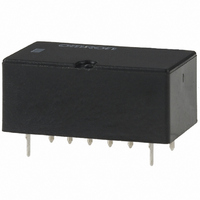
RELAY HI-FREQ SPDT 4.5VDC PCB
Manufacturer
Omron
Series
G6Yr
Datasheet
1.G6Y-1_DC5.pdf
(6 pages)
Specifications of G6Y-1 DC4.5
Relay Type
RF
Circuit
SPDT (1 Form C)
Contact Rating @ Voltage
0.01A @ 30VAC/DC
Coil Type
Standard
Coil Current
44.4mA
Coil Voltage
4.5VDC
Control On Voltage (max)
3.38 VDC
Control Off Voltage (min)
0.45 VDC
Mounting Type
Through Hole
Termination Style
PC Pin
Lead Free Status / RoHS Status
Lead free / RoHS Compliant
Other names
G6Y-1-DC4.5
G6Y1DC4.5
G6Y1DC45
G6Y1DC4.5
G6Y1DC45


■ Coil Ratings
Note: 1. The rated current and coil resistance are measured at a coil temperature of 23°C with a tolerance of ±10%.
■ Characteristics
Note: 1. The table above shows preliminary values.
Engineering Data
336
4.5
5
9
12
24
Contact resistance (See note 2.)
Operating time
Release time
Insulation resistance (See note 3.)
Dielectric strength
Vibration resistance
Shock resistance
Life expectancy
Ambient temperature
Ambient humidity
Weight
Rated voltage
■ Ambient Temperature vs.
Note: The maximum coil voltage refers to the maximum
(150)
140
180
160
120
100
200
Maximum Coil Voltage
(VDC)
0
2. The operating characteristics are measured at a coil temperature of 23°C.
3. The maximum voltage is the highest voltage that can be imposed on the relay coil instantaneously. It is not the maximum voltage that can
2. The contact resistance was measured with 100mA at 5VDC with a voltage drop method.
3. The insulation resistance was measured with a 500-VDC megohometer applied to the same points as those used for checking the dielectric strength.
be applied continuously.
value in a varying range of operating power voltage,
not a continuous voltage.
10
High Frequency Relay
20
44.4
40.0
22.2
16.7
8.3
30
Rated current
Ambient temperature (°C)
40
(mA)
50
60
70
(130)
80
101
125
405
720
2,880
Coil resistance
100 mΩ max.
10 ms max. (approx. 5 ms, typ.)
5 ms max. (approx. 1 ms, typ.)
100 MΩ min.
1,000 VAC, 50/60 Hz for 1 min between coil and contacts
500 VAC, 50/60 Hz for 1 min between contacts of same polarity
500 VAC, 50/60 Hz for 1 min between coil and ground and between contacts and ground
Destruction: 10 to 55 Hz, 1.5 mm double amplitude
Malfunction: 10 to 55 Hz, 1.5 mm double amplitude
Destruction: 1,000 m/s
Malfunction: 500 m/s
Mechanical: 1,000,000 operations min. (at 1,800 operations/hr)
Electrical: 300,000 operations min. (under rated load at 1,800 operations/hr)
Operating: −40°C to 70°C (with no icing)
Operating: 5 to 85%
Approx. 5 g
90 100
G6Y
(Ω)
Operating voltage
75% max. of rated
voltage
2
(approx. 50G)
2
(approx. 100G)
(V)
N.O. contact
Quantity Tested: 10 Units
Test Method: Shock was applied 3 times in each direction
1,200 min.
■ Resistance to Shock
1,200 min.
10% min. of rated
voltage
X
Release voltage
Z
N.C. contact
(V)
1,200 min.
1,000
with and without excitation and the level at
which the shock caused malfunction was
measured.
200
400
600
800
Y
Y'
1,000
800
200
1,200 min.
600
400
150% of rated volt-
age at 23°C
Maximum voltage
Y
Y'
Shock direction
X
Units: m/s
(V)
1,200 min.
1,200 min.
Z'
X'
X'
Z
Z'
2
Rating: 500 m/s
Approx. 200
Power consumption
(mW)
2
Related parts for G6Y-1 DC4.5
Image
Part Number
Description
Manufacturer
Datasheet
Request
R

Part Number:
Description:
RELAY HI-FREQ SPDT 5VDC PC MNT
Manufacturer:
Omron
Datasheet:
Part Number:
Description:
RELAY HI-FREQ SPDT 12VDC PC MNT
Manufacturer:
Omron
Datasheet:
Part Number:
Description:
RELAY HI-FREQ SPDT 24VDC PC MNT
Manufacturer:
Omron
Datasheet:

Part Number:
Description:
Low Signal Relays - PCB 900MHz SPDT 5VDC
Manufacturer:
Omron
Datasheet:
Part Number:
Description:
Low Signal Relays - PCB 900MHz SPDT 12VDC
Manufacturer:
Omron
Datasheet:

Part Number:
Description:
RELAY HI FREQ T/H
Manufacturer:
Omron
Datasheet:
Part Number:
Description:
LOW SIGNAL RF RELAY
Manufacturer:
Omron
Datasheet:
Part Number:
Description:
LOW SIGNAL RF RELAY
Manufacturer:
Omron
Datasheet:
Part Number:
Description:
LOW SIGNAL RF RELAY
Manufacturer:
Omron
Datasheet:

Part Number:
Description:
G6S-2GLow Signal Relay
Manufacturer:
Omron Corporation
Datasheet:
Part Number:
Description:
Compact, Low-cost, SSR Switching 5 to 20 A
Manufacturer:
Omron Corporation
Datasheet:
Part Number:
Description:
Manufacturer:
Omron Corporation
Datasheet: