G6L-1P-DC4.5 Omron, G6L-1P-DC4.5 Datasheet - Page 4
G6L-1P-DC4.5
Manufacturer Part Number
G6L-1P-DC4.5
Description
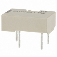
RELAY TELCOM SPST 4.5VDC PC MNT
Manufacturer
Omron
Series
G6Lr
Specifications of G6L-1P-DC4.5
Coil Type
Standard
Coil Current
40mA
Relay Type
Telecom
Circuit
SPST-NO (1 Form A)
Contact Rating @ Voltage
1A @ 24VDC
Coil Voltage
4.5VDC
Control On Voltage (max)
3.38 VDC
Control Off Voltage (min)
0.45 VDC
Mounting Type
Through Hole
Termination Style
PC Pin
Contact Form
1 Form C
Power Consumption
180 mW
Maximum Switching Current
1 A
Contact Rating
0.3 A at 125 VAC, 1 A at 24 VDC
Contact Configuration
SPST-NO
Contact Current Max
1A
Contact Voltage Ac Nom
125V
Contact Voltage Dc Nom
24V
Coil Voltage Vdc Nom
4.5V
Current, Rating
0.3⁄1 AAC⁄ADC
Dielectric Rating
1000 VAC @ 50⁄60 Hz for 1 Minute (Coil and Contacts), 750 VAC @ 50⁄60 Hz for 1 Minute (Contacts of Same Poles)
Dimensions
10.6 mm L x 7 mm W x 3.8 mm H
Function
General Purpose
Material, Contact
Ag (Au-Clad)
Number Of Pins
4
Standards
UL, CSA, FCC, RoHS
Temperature, Operating, Maximum
70 °C
Temperature, Operating, Minimum
-40 °C
Termination
Through Hole
Voltage, Control
4.5 VDC
Voltage, Rating
125 VAC
Lead Free Status / RoHS Status
Lead free / RoHS Compliant
Lead Free Status / RoHS Status
Lead free / RoHS Compliant, Lead free / RoHS Compliant
Other names
G6L1PDC4.5
G6L1PDC45
Z1227
G6L1PDC45
Z1227
Available stocks
Company
Part Number
Manufacturer
Quantity
Price
Company:

Part Number:
G6L-1P-DC4.5V
Manufacturer:
FUJITSU
Quantity:
12 000


G6L
Mutual Magnetic Interference
Energized
External Magnetic Interference
52
High-frequency Characteristics
(Isolation) (See note.)
Sample
100
Note:
−1,200
10
20
30
40
50
60
70
80
90
+30
+20
+10
−10
−20
−30
0
0
1
Sample: G6L-1F
Number of Relays: 5
S
High-frequency characteristics depend on the PCB to which the Relay is mounted. Always check these characteristics,
including endurance, in the actual machine before use.
−800
N
−400
10
External magnetic field (A/m)
−10
10
−5
Initial
stage
5
0
Installed in flush configuration
0
Must operate voltage
Must release voltage
Frequency (MHz)
100
Must operate voltage
Must release voltage
400
(Average value)
(Average value)
2.54 mm
800 1,200
5.08 mm
1,000
High-frequency Characteristics
(Insertion Loss) (See note.)
0.5
1.5
2.5
Mutual Magnetic Interference
Sample
0
1
2
−1,200
+30
+20
+10
−10
−20
−30
1
0
Sample: G6L-1F
Number of Relays: 5
S
Energized
−800
10
N
−400
External magnetic field (A/m)
−10
10
−5
Initial
stage
5
0
Installed in flush configuration
0
Must operate voltage
Must release voltage
Frequency (MHz)
100
Must operate voltage
Must release voltage
(Average value)
400
2.54 mm
(Average value)
800 1,200
1,000
5.08 mm
High-frequency Characteristics
(Return Loss, V.SWR) (See note.)
10
20
30
40
50
60
70
0
1
−1,200
+30
+20
+10
−10
−20
−30
0
Sample: G6L-1F
Number of Relays: 5
S
−800
10
−400
Return loss
N
V.SWR
External magnetic field (A/m)
Frequency (MHz)
0
100
(Average value)
Must operate voltage
Must release voltage
400
(Average value)
1,000
800 1,200
G6L
1.4
1.2
1
0.8
0.6
0.4
0.2
Related parts for G6L-1P-DC4.5
Image
Part Number
Description
Manufacturer
Datasheet
Request
R

Part Number:
Description:
LOW SIGNAL RELAY
Manufacturer:
Omron
Datasheet:
Part Number:
Description:
LOW SIGNAL RELAY
Manufacturer:
Omron
Datasheet:

Part Number:
Description:
Low Signal Relays - PCB LO PROF SPST 5VDC
Manufacturer:
Omron
Datasheet:
Part Number:
Description:
Low Signal Relays - PCB LO PROF SPST 12VDC
Manufacturer:
Omron
Datasheet:
Part Number:
Description:
RELAY TELCOM SPST 3VDC PC MNT
Manufacturer:
Omron
Datasheet:
Part Number:
Description:
RELAY TELCOM SPST 24V PCB
Manufacturer:
Omron
Datasheet:

Part Number:
Description:
RELAY, PCB, SPNO, 24VDC
Manufacturer:
Omron
Datasheet:
Part Number:
Description:
RELAY, PCB, SPNO, 3VDC
Manufacturer:
Omron
Datasheet:
Part Number:
Description:
RELAY, PCB, SPNO, 5VDC
Manufacturer:
Omron
Datasheet:

Part Number:
Description:
RELAY, SMD, SPNO, 12VDC
Manufacturer:
Omron
Datasheet: