NF2EB-24V Panasonic Electric Works, NF2EB-24V Datasheet - Page 2
NF2EB-24V
Manufacturer Part Number
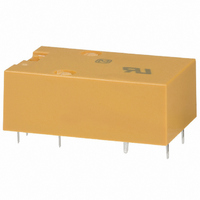
NF2EB-24V
Description
RELAY 2A 24VDC AMB FLATPACK PCB
Manufacturer
Panasonic Electric Works
Series
NFr
Type
Flat Pack Relayr
Datasheet
1.NF2EB-5V.pdf
(3 pages)
Specifications of NF2EB-24V
Relay Type
General Purpose
Circuit
DPDT (2 Form C)
Contact Rating @ Voltage
2A @ 30VDC
Coil Type
Standard
Coil Current
20mA
Coil Voltage
24VDC
Control On Voltage (max)
19.2 VDC
Control Off Voltage (min)
2.4 VDC
Mounting Type
Through Hole
Termination Style
PC Pin
Relay Construction
Non-Latching
Contact Arrangement
DPDT
Coil Voltage Dc
24V
Contact Form
2 Form C
Voltage Rating (vdc)
220V
Voltage Rating (vac)
220V
Dropout Volt (min)
2.4VDCV
Coil Resistance
2kohm
Pick-up Voltage (max)
19.2VDC
Maximum Power Rating
60W/100VA
Operate Time
15ms
Contact Current Rating
2A
Contact Material
Ag/Au Clad
Coil Suppression Diode
No
Push To Test Button
No
Led Indicator
No
Seal
Sealed
Product Height (mm)
11.1mm
Product Depth (mm)
20mm
Product Length (mm)
30.2mm
Operating Temp Range
-40C to 65C
Pin Count
9
Mounting Style
Through Hole
Lead Free Status / RoHS Status
Lead free / RoHS Compliant
Other names
255-2240
NF2EB-24V
NF2EB-24V
Available stocks
Company
Part Number
Manufacturer
Quantity
Price
Company:

Part Number:
NF2EB-24V
Manufacturer:
ARM
Quantity:
2 698
Company:
Part Number:
NF2EB-24V
Manufacturer:
MORNSUN
Quantity:
2 300


ORDERING INFORMATION
(Notes) 1. For VDE recognized types, add suffix VDE.
(Notes)
(Notes)
TYPES AND COIL DATA (at 25°C 77°F)
DIMENSIONS
2 Form C
4 Form C
2
NF2EB-5V
NF2EB-6V
NF2EB-12V
NF2EB-24V
NF2EB-48V
NF4EB-5V
NF4EB-6V
NF4EB-12V
NF4EB-24V
NF4EB-48V
Part No.
Contact arrangement
.425±.012
.425±.012
10.8±0.3
10.8±0.3
2. For UL/CSA recognized type, add suffix-A, as NF2EB-12V-A whose ground terminal is cut off.
3. Standard packing Carton: 20 pcs.; Case: 200 pcs.
.012
.012
2: 2 Form C
4: 4 Form C
0.3
0.3
.130
.130
3.3
3.3
Nominal voltage,
Resin rise
max. 0.5
max.
Resin rise
max. 0.5
max.
4-0.8 dia.
4-0.8 dia.
Stand-off
Stand-off
.031 dia.
.031 dia.
.020
.020
V DC
12
24
48
12
24
48
Ground terminal
Ground terminal
5
6
5
6
N.O.
N.O.
N.C.
N.C.
Type classification
Ex. NF
1.189
1.189
30.2
20.6
.811
30.2
20.6
.811
Pick-up voltage,
EB: Standard
V DC (max.)
Coil terminal
Coil terminal
19.2
38.4
19.2
38.4
Common terminal
Common terminal
4.0
4.8
9.6
4.0
4.8
9.6
4
.512
13.6
.535
13
.787
24.6
.969
20
EB
V DC (min.)
Terminal dimensions (except soldering)
Width: 0.8
Thickness: 0.3
MBB contact position
NF4-2M: terminals 6-7-8, 9-10-11
NF4-2M: terminals 6-7-8, 3-4-5, 12-13-14, 9-10-11
Drop-out
voltage,
Terminal dimensions (except soldering)
Width: 0.8
Thickness: 0.3
MBB contact position
NF2-2M: terminal 6-7-8, 3-4-5
Nil: Form C type
2M: 2MBB (2 Form D)
4M: 4MBB (4 Form D)
0.5
0.6
1.2
2.4
4.8
0.5
0.6
1.2
2.4
4.8
MBB function
.031
.031
General tolerance: ±0.5
.012
4M
(Except for the cover height)
.012
V DC (at 40°C)
Max. allowable
Schematic
Schematic
voltage,
10.5
21
42
84
17.0
34
68
8.7
7
8.5
48V
Coil voltage (DC)
±.020
5, 6, 12,
24, 48 V
Coil resistance,*
2,000
7,000
1,200
4,200
Ω
137
500
330
90
53
90
1
5.1±0.2
.2±.008
5.1±0.2
.2±.008
PC board pattern (Copper-side view)
PC board pattern (Copper-side view)
.193
.193
.083
.083
4.9
4.9
2.1
2.1
Relay
outline
Relay
outline
Nil: Gold-clad silver
1: Gold-cap over silver palladium
operating power,
1.13
.044
1.13
.044
Nominal
mW
278
260
290
290
330
472
400
440
480
550
ds_61014_en_nf: 040804J
7.6±0.2
.3±.008
7.6±0.2
.3±.008
Contact metarial
*Less than 1,000 Ω:
*More than 1,000 Ω:
1.3
.051 DIA.
1.3
.051 DIA.
12.7±0.2
12.7±0.2
.5±.008
.5±.008
+0
–0.3
+0
–0.3
(2.54)
(.100)
(2.54)
(.100)
0.071
0.093
0.338
1.29
4.12
0.029
0.070
0.22
0.77
2.22
Open
Inductance, H
+0
–.012
+0
–.012
7.6±0.2
.3±.008
7.6±0.2
.3±.008
Armarure
mm
Close
(2.54)
(.100)
(2.54)
(.100)
0.071
0.094
0.344
1.31
4.18
0.029
0.071
0.23
0.79
2.25
1.13
.044
1.13
.044
NF
±10%
±15%
inch
Related parts for NF2EB-24V
Image
Part Number
Description
Manufacturer
Datasheet
Request
R

Part Number:
Description:
RELAY FLATPACK DPDT 2A 5VDC PCB
Manufacturer:
Panasonic Electric Works
Datasheet:
Part Number:
Description:
RELAY 2A 12VDC AMB FLATPACK PCB
Manufacturer:
Panasonic Electric Works
Datasheet:
Part Number:
Description:
RELAY FLATPACK DPDT 2A 6VDC PCB
Manufacturer:
Panasonic Electric Works
Datasheet:
Part Number:
Description:
RELAY FLATPACK DPDT 2A 6VDC PCB
Manufacturer:
Panasonic Electric Works
Datasheet:
Part Number:
Description:
RELAY 2A 48VDC AMB FLATPACK PCB
Manufacturer:
Panasonic Electric Works
Datasheet:
Part Number:
Description:
RELAY 2A 12VDC AMB FLATPACK PCB
Manufacturer:
Panasonic Electric Works
Datasheet:
Part Number:
Description:
RELAY 2A 24VDC AMB FLATPACK PCB
Manufacturer:
Panasonic Electric Works
Datasheet:
Part Number:
Description:
RELAY 2A 6VDC AMBER FLATPACK PCB
Manufacturer:
Panasonic Electric Works
Datasheet:
Part Number:
Description:
RELAY 2A 48VDC AMB FLATPACK PCB
Manufacturer:
Panasonic Electric Works
Datasheet:
Part Number:
Description:
RELAY 2A 24VDC AMB FLATPACK PCB
Manufacturer:
Panasonic Electric Works
Datasheet:

Part Number:
Description:
Manufacturer:
Panasonic Electric Works
Datasheet:
Part Number:
Description:
Manufacturer:
Panasonic Electric Works
Datasheet:

Part Number:
Description:
CONN SOCKET P4 .4MM 50POS SMD
Manufacturer:
Panasonic Electric Works
Datasheet:
Part Number:
Description:
CONN SOCKET .8MM 16POS SMD
Manufacturer:
Panasonic Electric Works
Datasheet:
Part Number:
Description:
CONN HEADER .8MM 16POS SMD
Manufacturer:
Panasonic Electric Works
Datasheet: