Y92F-30 Omron, Y92F-30 Datasheet - Page 13
Y92F-30
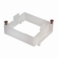
Manufacturer Part Number
Y92F-30
Description
ADAPTER PANEL MNT FOR H3CR/H5CX
Manufacturer
Omron
Type
Panel Mounting Adaptersr
Specifications of Y92F-30
Accessory Type
Panel Mount Adapter, Frame
Mounting Type
Panel Mount
Rohs Compliant
Yes
Length
58 mm
Mounting Hole Size
45 mm
For Use With/related Products
Multiple Series
For Use With
Z3000 - RELAY TIMER DGTL SPDT 12-24VDCZ2999 - RELAY TIMER DGTL SPDT 100/240VACZ2998 - RELAY TIMER DGTL SPDT 100/240VACH3CR-A8E AC100-240/DC100-125 - RELAY ANALOG SET DPDT 8PINZ2815 - RELAY REPEAT CYCLE ANALOG 30HRSZ2387 - RELAY TIMER 0-12SEC OFF-DELAYZ2386 - RELAY TIMER 0-12MIN OFF-DELAYZ2385 - RELAY REPEAT CYCLE ANALOG 30HRSZ2384 - RELAY REPEAT CYCLE ANALOG 300HRSZ2381 - RELAY ANALOG SET DPDT 8PINZ2380 - RELAY ANALOG SET DPDT 8PINZ2379 - RELAY ANALOG SET DPDT 8PINZ2366 - RELAY REPEAT CYCLE ANLG 30HRSZ2382 - RELAY REPEAT CYCLE ANLG 30HRSZ997 - RELAY TIMER ANALOG 24VDC/ACZ2358 - RELAY REPEAT CYCLE ANLG 30HRSZ876 - RELAY TIMER DPDT ANALOG 120\240V
Lead Free Status / RoHS Status
Lead free / RoHS Compliant
Color
-
Lead Free Status / Rohs Status
Lead free / RoHS Compliant
Other names
Y92F30
Z885
Z885


H5CR
Note:
Mode
Run mode
Setting mode
SETTING ITEM TABLE
1. Changes made in setting mode become effective when run mode is entered.
2. The time range setting appears first when setting mode is entered.
Setting item
Set value
Time range
UP/DOWN mode
Output mode
Output time
Input signal time
Key protect level
Description
Compared to the present value.
Determines the timing of the control
output according to the output mode.
Determines the timing range.
Selects the display that shows elapsed
time (UP) or time remaining (DOWN).
Determines the control output type.
(Refer to the present value vs. output
diagrams on pages 5 to 8.)
Determines the duration of the control
output. Will be displayed when the
output mode is A, A-1, A-2, A-3, B,
or B-1. Will not be displayed in
output modes D, E, or F.
Changes the duration of the control
and reset input signals.
Locks certain keys to prevent accidental
operation. The key protection level,
kP-1 to kP-4, determines which keys are
locked when the key protection input
is ON. The locked keys are crossed
out in the diagram at right.
13
Setting procedure
Sequence when changing a digit using the
increment keys (1 to 4).
Change the timing range with the increment
keys (1 to 4).
Select UP/DOWN with the increment keys
(1 to 4).
Sequence when changing the mode using the
increment keys (1 to 4).
Change the output time with the increment keys
(1 to 4).
Change the duration with increment keys
(1 to 4).
Sequence when changing the key protect
level using the increment keys (1 to 4).
<KP–1>
<KP–3>
<KP–2>
<KP–4>
H5CR
Related parts for Y92F-30
Image
Part Number
Description
Manufacturer
Datasheet
Request
R

Part Number:
Description:
Solid-state Timer
Manufacturer:
OMRON [Omron Electronics LLC]
Datasheet:

Part Number:
Description:
ADAPTER FOR H7E
Manufacturer:
Omron
Datasheet:

Part Number:
Description:
Panel-Mounting Adapter
Manufacturer:
Omron
Datasheet:
Part Number:
Description:
H5S TRACK MNT ADAPTER
Manufacturer:
Omron
Datasheet:

Part Number:
Description:
Low-Cost Plug-In Timer W/Large Switching Capacity Solid-State Accessory, Panel Mounting Adapter
Manufacturer:
Omron
Datasheet:
Part Number:
Description:
ADAPTER H3CR 78MM BODY
Manufacturer:
Omron
Datasheet:
Part Number:
Description:
ADAPTER H3CR 78MM BODY
Manufacturer:
Omron
Datasheet:
Part Number:
Description:
PANEL ADAPTER/H3M
Manufacturer:
Omron
Datasheet:

Part Number:
Description:
FLUSH MNT ADAPTER
Manufacturer:
Omron
Datasheet:
Part Number:
Description:
MOUNTING BASE
Manufacturer:
Omron
Datasheet:
Part Number:
Description:
ADAPTER H3CR 66MM BODY
Manufacturer:
Omron
Datasheet:
Part Number:
Description:
G6S-2GLow Signal Relay
Manufacturer:
Omron Corporation
Datasheet:
Part Number:
Description:
Compact, Low-cost, SSR Switching 5 to 20 A
Manufacturer:
Omron Corporation
Datasheet: