PTC-04-90316 Melexis Inc, PTC-04-90316 Datasheet
PTC-04-90316
Specifications of PTC-04-90316


Related parts for PTC-04-90316


PTC-04-90316 Summary of contents
Page 1
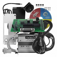
... Programmer Unit (Full Set: including adapter, cables, software, default DB) Default Daughter Board Other Daughter Boards for future products 19”Rack with build in x number of PTC04 Description Magnetic utility for evaluating samples on PTC04 PCB with 4SIP socket PCB with SO Socket and TSSOP Socket ...
Page 2
... Functional Diagram 2. Description The PTC-04 programmer was designed for efficient, precise calibration of the Melexis families of programmable ICs. The programmer is designed to be easily adapted to a standard PC and to an application module to allow calibration of programmable sensor ICs within the operating environment. The PTC-04 programmer contains its own programmable power supply and measurement circuitry. The ...
Page 3
... ETTINGS 11. MEASUREMENT SYSTEM ................................................................................................................. 16 11.1. C ....................................................................................................................................................16 HANNELS 11.2. C ........................................................................................................................................16 ONVERSION TIME 11.3. A ...................................................................................................................................................16 CCURACY 12. ESD PRECAUTIONS........................................................................................................................... 16 13. MECHANICAL OUTLINES.................................................................................................................. 17 14. DISCLAIMER ....................................................................................................................................... 18 3901290014501 Rev. 1.5 Programmer for Melexis PTC devices TABLE OF CONTENTS ................................................................................................................................. 1-3 ...................................................................................5 URRENT OWER UPPLY S 4 .......................................................................................................6 OWER UPPLY .................................................................................................................................7 ...................................................................................................................8 ....................................................................................................................10 .................................................................................................................11 Page ...
Page 4
... A Parameter DC System Power Supply System Current Consumption Daughter Board Analog Power Supply * Daughter Board Digital Power Supply * Depends on the DC System Power Supply 3901290014501 Rev. 1.5 Programmer for Melexis PTC devices 48V Yes 1 A Fused 34 V 500mA °C 0°C – 55 ° ext = 48V (unless otherwise specified) ...
Page 5
... Voltage Source Swing Vout PPS1-PPS3 Voltage Source Accuracy Voltage Source Slew Rate * Depends on the DC System Power Supply 3901290014501 Rev. 1.5 Programmer for Melexis PTC devices C, V ext = 48V (unless otherwise specified) Test Conditions Unloaded Unloaded I out = 10mA I out = 100mA I out = 500mA ...
Page 6
... PPS4 Voltage Source Accuracy Voltage Source Slew Rate Using 8 bit Fast DAC 3901290014501 Rev. 1.5 Programmer for Melexis PTC devices C, V ext = 48V (unless otherwise specified) Remarks When Fast DAC = 255 Divider between Pos and Neg voltage This is taken by changing the ...
Page 7
... A Parameter Symbol Voltage Source Program Rate Voltage Source Noise Current Measurement Sample Time 3901290014501 Rev. 1.5 Programmer for Melexis PTC devices C, V ext = 48V (unless otherwise specified) Test Conditions PPS1-3 PPS4 PPS1-3 PPS4 PPS1-3 PPS4 C, V ext = 48V (unless otherwise specified) ...
Page 8
... Unique Features 6.1. Mini Tester Due to the architecture of the Hardware in combination with the Software, the PTC04 can be used as a mixed mode tester. (With limited performance) There are library routines (DLL) available in order to interface with any software language. (C, C++, Visual Basic, Lab view, Excel … ...
Page 9
... Power Supplies The Power Supply input connector is a single input to supply the whole PTC. The Input supply requires a minimum of 24 volts and can tolerate a maximum of 48 volts not recommended to use a higher voltage than needed for the application. There’s an internal fuse (on the main board order to avoid damage when improperly used ...
Page 10
... Figure 7-2 7.5. LED Indicators Two Led indicators will help the user to check the status of the PTC The red led shows that the core inside has power The green led will show a busy status. If the Programmer is executing a job, the led will be on. ...
Page 11
... Daughter board Connectors The main board has two connectors to the interface with the application. The PTC allows the addition of a full PCB in between the main board and the interface. This daughter board can be mounted on the two connectors. In some exceptional cases, a daughter board contains only a few wires from the Analog connector to the application connector ...
Page 12
... Read : A negative pulse will indicate a sampling of the data on the Data Bus Write : A Negative pulse will indicate when data is available on the Data Bus This signal goes low by powering the PTC or by pressing the reset button. This line can be pulled low by application. Check firmware documentation for resetting by software. ...
Page 13
... The future of our products is not known and building a universal programmer will not be possible to survive more than a few years. For this reason, a flexibility is build in by having a Daughter board (abbreviation: DB) as interface between PTC04 and the application connector. On this way, special needs can be fulfilled. ...
Page 14
... DB9-Male Description 2 RxD 3 TxD 5 GND (At the Computer and at the PTC04) 9 PIN D-SUB MALE at the Computer. 9.2. Cable The cable between PTC and Host standard null-modem cable for RS232C Cable Description: DB9-FEM DB9-FEM 9.3. Settings The microprocessor core has a fixed setting to communicate with the host. ...
Page 15
... GND 10.2. Cable Default: USB A (at the Connector) to plug into a PC USB B (at the Connector) to plug into the PTC04 Series "A" plugs are used towards the host system and series "B" plugs are used towards the USB device. 10.3. Settings 2 drivers have to be installed and are available on the Software CD 3901290014501 Rev ...
Page 16
... In general the conversion time depends on the loaded firmware version. Theoretically, a full conversion to a floating real value takes about 4ms if the filter is put at 100 samples. 11.3. Accuracy To preserve the accuracy of the PTC04, Melexis recommends checking the tolerance of the PTC04 once a year. 12. ...
Page 17
... Mechanical Outlines 3901290014501 Rev. 1.5 Programmer for Melexis PTC devices Page PTC04 Data Sheet PTC04 May 10 ...
Page 18
... For the latest version of this document our website at Or for additional information contact Melexis Direct: Europe, Africa, Asia: Phone: +32 13 670 495 E-mail: sales_europe@melexis.com 3901290014501 Rev. 1.5 Programmer for Melexis PTC devices www.melexis.com ISO/TS 16949 and ISO14001 Certified Page PTC04 America: Phone: +1 603 223 2362 E-mail: sales_usa@melexis ...