SUPERPRO 500P Xeltek, SUPERPRO 500P Datasheet - Page 37
SUPERPRO 500P
Manufacturer Part Number
SUPERPRO 500P
Description
PROGRAMMER UNIVERSAL 48-PIN
Manufacturer
Xeltek
Series
SuperPro 500Pr
Type
Universal, Stand Aloner
Datasheet
1.CX1016.pdf
(91 pages)
Specifications of SUPERPRO 500P
Contents
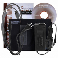
Programmer with 48-Pin DIP Socket, AC Adapter, Software CD, USB Cable, Users Manual
Ic Product Type
Programmer, Universal
Ic Interface Type
USB
No. Of Devices Supported
22462
Kit Contents
SuperPro 500P Programmer, AC Adapter, CD
Rohs Compliant
Yes
For Use With/related Products
E/EPROM, FLASH, PLD, Micros and more listed on Device Sheet, 21,000+ Devices Supported
For Use With
415-1029 - SOCKET ADAPTER FOR SDIP42415-1028 - SOCKET ADAPTER FOR TQFP32415-1027 - SOCKET ADAPTER FOR TSOP56415-1025 - SOCKET ADAPTER FOR SOIC20415-1024 - SOCKET ADAPTER FOR TSOP40415-1023 - SOCKET ADAPTER FOR SOP44415-1022 - SOCKET ADAPTER FOR TSOP56415-1019 - SOCKET ADAPTER FOR SOIC16/SOIC8415-1018 - SOCKET ADAPTER FOR SOIC28415-1015 - SOCKET ADAPTER FOR PLCC28415-1014 - SOCKET ADAPTER FOR PLCC20415-1013 - SOCKET ADAPTER FOR PLCC32415-1017 - SOCKET ADAPTER FOR PLCC44
Lead Free Status / RoHS Status
Lead free by exemption / RoHS compliant by exemption
Other names
415-1047
SP500P
SP500P


Chip Insertion – None‐DIP Encapsulation
Socket adapters are available for other encapsulations, including PLCC, QFP, and
SOIC. Refer to the Adapter Information on the Device Information screen. The
insertion follows the position of pin 1.
To identify pin 1 of the chip, look for a solid square or dot on the chip that gives
the information about the chip. It also indicates the first pin of the chip.
Direct‐connect
For 144‐pins adapters, connect directly to programmers.
Indirect‐connect
For 48‐pins adapters, insert into DIP of the programmer.
Device Configuration Word
Some single‐chip microcomputers allow special working modes, such as the
storage area mapping, the watchdog time, the clock, or the encryption. Set these
special modes through the Device Configuration Word option.
The user files contain the configuration words of some devices. When you load
these files, the system automatically loads the configuration words into the
configuration word buffer. However, you must select the configuration words for
some devices manually.
Select Device Configuration Word from the Device menu to open the
ConfigWord dialog box. The following sample illustration shows the
Superpro
Note: 1. Generally, the pins of the chip are downward when they are inserted.
Important: The device configuration word varies from device to device. Refer to
However, as for the chip PLCC20, its pins should be upward.. This
insertion is called the ‚Dead Bug‛ method.
2. SUPERPRO/5000 and SUPERPRO/5000E support 144 pins while
SUPERPRO/501S and SUPERPRO/500P only support 48 pins.
®
5000 User’s Guide
the device data manual for more information about the configuration
words. Set the configuration words according to the requirements of
your target system. Otherwise, you cannot use the device normally
even if it is normal when preparing and verifying the program.
:
37
Related parts for SUPERPRO 500P
Image
Part Number
Description
Manufacturer
Datasheet
Request
R

Part Number:
Description:
PROGRAMMER UNIVERSAL 48-PIN
Manufacturer:
Xeltek
Datasheet:

Part Number:
Description:
SUPERPRO 501S N*CLUSTER Gang Programmer
Manufacturer:
Xeltek


Part Number:
Description:
PROGRAMMER UNIV STANDALONE W/USB
Manufacturer:
Xeltek
Datasheet:


Part Number:
Description:
SUPERPRO 3000U IC Device Programmer In X4 CLUSTER
Manufacturer:
Xeltek

Part Number:
Description:
SUPERPRO 3000U N*CLUSTER Gang Programmer
Manufacturer:
Xeltek


Part Number:
Description:
SOCKET ADAPTER FOR SOIC16/SOIC8
Manufacturer:
Xeltek
Datasheet:

Part Number:
Description:
Flash 256MB COMPACT FLASH CARD
Manufacturer:
Xeltek