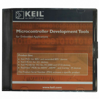
MDK-ARM Keil, MDK-ARM Datasheet - Page 143

MDK-ARM
Manufacturer Part Number
MDK-ARM
Description
KIT REALVIEW MCU DEVELOPMENT
Manufacturer
Keil
Type
Compiler and IDEr
Specifications of MDK-ARM
For Use With/related Products
ARM MCUs
Lead Free Status / RoHS Status
Lead free / RoHS Compliant
- Current page: 143 of 156
- Download datasheet (3Mb)
Getting Started: Building Applications with RL-ARM
143
On the CAN bus, logic zero is represented by a maximum voltage difference
called “Dominant.” Logic one (1) is represented by a bus idle state called
“Recessive”. A dominant bit will overwrite a recessive bit. Therefore, if ten
nodes write recessive and one writes dominant, then each node will read back a
dominant bit. The CAN bus can achieve bit rates of up to a maximum of 1Mb/s.
Typically, this can be achieved over 40 meters of cable. Longer cable lengths
can be achieved by reducing the bit rate. In practice, you can get at least 1,500
meters with the standard drivers at 10 Kbit/s.
CAN Message Frames
The CAN bus has two message objects, which may be generated by the
application software. These are the message frame and the remote request frame.
The message frame is used to transfer data around the network. The message
frame is shown below.
The CAN controller forms the message frame. The application software provides
the data bytes, the message identifier, and the RTR bit.
The message frame starts with a dominant bit to mark the start of frame. Next is
the message identifier, which may be up to 29 bits long. The message identifier
is used to label the data being sent in the message frame. CAN is a
producer/consumer protocol or broadcast protocol. A given message is produced
from one unique node and then may be consumed by any number of nodes on the
network simultaneously. It is also possible to do point-to-point communication
by making only one node interested in a given identifier. Then a message can be
sent from the producer node to one given consumer node on the network. In the
message frame, the RTR bit is always set to zero (this field will be discussed
shortly). The Data Length Code (DLC) field contains an integer between zero
and eight, and indicates the number of data bytes being sent in this message
frame. You can send a maximum of 8 bytes in the message payload. It is also
possible to truncate the message frame to save bandwidth on the CAN bus. After
the 8 bytes of data, there is a 15-bit Cyclic Redundancy Check (CRC). This
Related parts for MDK-ARM
Image
Part Number
Description
Manufacturer
Datasheet
Request
R

Part Number:
Description:
KIT REALVIEW MCU DEVELOPMENT
Manufacturer:
Keil
Datasheet:

Part Number:
Description:
Development Software SUPPORT EXTENSION FOR MDK-ARM-B
Manufacturer:
Keil Software

Part Number:
Description:
Development Software SUPPORT EXTENSION FOR MDK-ARM
Manufacturer:
Keil Software

Part Number:
Description:
KIT REALVIEW MCU DEVELOPMENT
Manufacturer:
Keil
Datasheet:

Part Number:
Description:
Development Software MCU DEV KIT FOR ARM UPG TO FLOATING LIC
Manufacturer:
Keil Tools

Part Number:
Description:
Development Software MCU DEV KIT FOR ARM W/ FLOATING LICENSE
Manufacturer:
Keil Software

Part Number:
Description:
Development Software MCU DEV KIT FOR ARM uVISION & C++ & RTX
Manufacturer:
Keil Tools

Part Number:
Description:
Development Software SUPP LICENSE RENEWAL 90+ DAYS NO TECH SUP
Manufacturer:
Keil Software
Part Number:
Description:
KEIL C-COMPILER INTERNATIONAL
Manufacturer:
Silicon Laboratories Inc

Part Number:
Description:
BOARD EVAL FOR LPC213X ARM MCU
Manufacturer:
NXP Semiconductors
Datasheet:
Part Number:
Description:
K60N512 Keil Tower Kit
Manufacturer:
Freescale Semiconductor
Datasheet:


