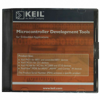
MDK-ARM Keil, MDK-ARM Datasheet - Page 142

MDK-ARM
Manufacturer Part Number
MDK-ARM
Description
KIT REALVIEW MCU DEVELOPMENT
Manufacturer
Keil
Type
Compiler and IDEr
Specifications of MDK-ARM
For Use With/related Products
ARM MCUs
Lead Free Status / RoHS Status
Lead free / RoHS Compliant
- Current page: 142 of 156
- Download datasheet (3Mb)
142
Chapter 6. RL-CAN Introduction
The two most popular of these application layer standards are CANopen and
DeviceNet. The sole purpose of these standards is to provide interoperability
between different Original Equipment Manufacturers’ (OEM) equipment. If you
are developing your own closed system, then you do not need these application
layer protocols. You are free to implement your own proprietary protocol, which
many developers do.
CAN Node Design
A typical CAN node is shown in
the picture. Each node consists
of a microcontroller and a CAN
controller. The CAN controller
may be fabricated on the same
silicon as the microcontroller.
Alternatively, it may be a
standalone controller in a
separate chip from the
microcontroller. The CAN
controller is interfaced to the
twisted pair by a CAN
Transceiver. The twisted pair is
terminated at either end by a 120
Ohm resistor. The most
common mistake with a first
CAN network is to forget the
terminating resistors and then
nothing works.
The CAN controller has separate
transmit and receive paths to and
from the Physical Layer device.
This is an important feature of
the CAN node. Therefore, as the
node is writing to the bus, it is
also listening back. This is the basis of the message arbitration and it also
contributes to the error detection. The two logic levels, which are written on to
the twisted pair, are defined as follows; a logic one is represented by bus idle,
with both wires held half way between 0 and V
. A logic zero is represented by
CC
both wires being differentially driven.
Related parts for MDK-ARM
Image
Part Number
Description
Manufacturer
Datasheet
Request
R

Part Number:
Description:
KIT REALVIEW MCU DEVELOPMENT
Manufacturer:
Keil
Datasheet:

Part Number:
Description:
Development Software SUPPORT EXTENSION FOR MDK-ARM-B
Manufacturer:
Keil Software

Part Number:
Description:
Development Software SUPPORT EXTENSION FOR MDK-ARM
Manufacturer:
Keil Software

Part Number:
Description:
KIT REALVIEW MCU DEVELOPMENT
Manufacturer:
Keil
Datasheet:

Part Number:
Description:
Development Software MCU DEV KIT FOR ARM UPG TO FLOATING LIC
Manufacturer:
Keil Tools

Part Number:
Description:
Development Software MCU DEV KIT FOR ARM W/ FLOATING LICENSE
Manufacturer:
Keil Software

Part Number:
Description:
Development Software MCU DEV KIT FOR ARM uVISION & C++ & RTX
Manufacturer:
Keil Tools

Part Number:
Description:
Development Software SUPP LICENSE RENEWAL 90+ DAYS NO TECH SUP
Manufacturer:
Keil Software
Part Number:
Description:
KEIL C-COMPILER INTERNATIONAL
Manufacturer:
Silicon Laboratories Inc

Part Number:
Description:
BOARD EVAL FOR LPC213X ARM MCU
Manufacturer:
NXP Semiconductors
Datasheet:
Part Number:
Description:
K60N512 Keil Tower Kit
Manufacturer:
Freescale Semiconductor
Datasheet:


