DK-DSP-2C70N Altera, DK-DSP-2C70N Datasheet - Page 26
DK-DSP-2C70N
Manufacturer Part Number
DK-DSP-2C70N
Description
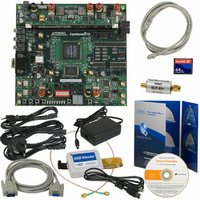
DSP KIT W/CYCLONE II EPS2C70N
Manufacturer
Altera
Series
Cyclone® IIr
Type
DSPr
Datasheet
1.DK-DSP-2C70N.pdf
(32 pages)
Specifications of DK-DSP-2C70N
Contents
Dev Board, Quartus®II Web Edition, Cables, Accessories, Reference Designs and Demos
For Use With/related Products
Cyclone ll 2C70N
Lead Free Status / RoHS Status
Lead free / RoHS Compliant
Other names
544-1699
Available stocks
Company
Part Number
Manufacturer
Quantity
Price


Testing the Board Using the Factory Design
Figure 2–7. Factory Design Functional Block Diagram
2–16
DSP Development Kit, Cyclone II Edition
Clock Signal
100 MHz
Sine Wave Source
Sine Wave Source
10 MHz
1 MHz
NCO
NCO
1
Testing LEDs & Pushbutton Switches
In the factory design, switches SW2 through SW5 (USER_PB3 through
USER_PB0) are connected via inverters to LEDs D9 through D6
(USER_LED0 to USER_LED3, respectively). When a switch is pressed, the
corresponding LED turns off. You can test this functionality on the
Cyclone II DSP development board.
Performing the A/D & D/A Converter Performance Test
To test the A/D and D/A converter performance using the factory
design, follow these steps:
1.
2.
3.
Cyclone II Device (U18)
“Configuring the Board” on page 2–17
“Collecting Data Using the SignalTap II Logic Analyzer” on
page 2–20
“Analyzing the Data in the MATLAB Software” on page 2–20
The design files for the factory design are installed from the DSP
Development Kit, Cyclone II Edition Version 6.0.1 CD-ROM in the
directory:
<path>\CycloneII_DSP_Kit-v6.0.1\Examples\
FactoryDesign_ChA
Getting Started User Guide
comb[13..0]
SignalTap II
a2db[11..0]
comb[13..0]
DAC904E Device
ADS5520 device
DAC A
ADC A
(U25)
(U26)
Altera Corporation
DAC CHANNEL A out (J31)
SMA Connector
ADC CHANNEL A in (J32)
SMA Connector
August 2006
SMA Cable and
SLP-50 Low-pass
Filter
Related parts for DK-DSP-2C70N
Image
Part Number
Description
Manufacturer
Datasheet
Request
R

Part Number:
Description:
KIT DEV DSP CYCLONE III EDITION
Manufacturer:
Altera
Datasheet:

Part Number:
Description:
KIT DEV DSP STRATIX III
Manufacturer:
Altera
Datasheet:

Part Number:
Description:
DSP KIT W/STRATIX II EP2S60N
Manufacturer:
Altera
Datasheet:

Part Number:
Description:
DSP PRO KIT W/SII EP2S180N
Manufacturer:
Altera
Datasheet:

Part Number:
Description:
CYCLONE II STARTER KIT EP2C20N
Manufacturer:
Altera
Datasheet:

Part Number:
Description:
KIT DEV NIOS II CYCLONE III ED.
Manufacturer:
Altera
Datasheet:

Part Number:
Description:
KIT DEV STRATIX IV 4SGX230N/C2
Manufacturer:
Altera
Datasheet:

Part Number:
Description:
KIT DEV MAXII W/EPM 1270N
Manufacturer:
Altera
Datasheet:

Part Number:
Description:
KIT STARTER CYCLONE III EP3C25
Manufacturer:
Altera
Datasheet:

Part Number:
Description:
KIT STARTER CYCLONE IV GX
Manufacturer:
Altera
Datasheet:


Part Number:
Description:
CPLD, EP610 Family, ECMOS Process, 300 Gates, 16 Macro Cells, 16 Reg., 16 User I/Os, 5V Supply, 35 Speed Grade, 24DIP
Manufacturer:
Altera Corporation
Datasheet:
Part Number:
Description:
CPLD, EP610 Family, ECMOS Process, 300 Gates, 16 Macro Cells, 16 Reg., 16 User I/Os, 5V Supply, 15 Speed Grade, 24DIP
Manufacturer:
Altera Corporation
Datasheet: