DK-DSP-2C70N Altera, DK-DSP-2C70N Datasheet - Page 25
DK-DSP-2C70N
Manufacturer Part Number
DK-DSP-2C70N
Description
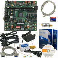
DSP KIT W/CYCLONE II EPS2C70N
Manufacturer
Altera
Series
Cyclone® IIr
Type
DSPr
Datasheet
1.DK-DSP-2C70N.pdf
(32 pages)
Specifications of DK-DSP-2C70N
Contents
Dev Board, Quartus®II Web Edition, Cables, Accessories, Reference Designs and Demos
For Use With/related Products
Cyclone ll 2C70N
Lead Free Status / RoHS Status
Lead free / RoHS Compliant
Other names
544-1699
Available stocks
Company
Part Number
Manufacturer
Quantity
Price


Getting Started
Testing the
Board Using the
Factory Design
Altera Corporation
August 2006
Put the Cyclone II DSP development board in SAFE configuration mode
by putting a jumper on J29, pins 1 and 2. Then apply power and the
Cyclone II device will be configured with the factory design stored in the
EPCS64 flash memory, serial configuration device (U17). When
configuration is complete, LEDs D9 through D5 (USER_LED0 through
USER_LED4, respectively), flash yellow, functioning as a binary counter
that counts down to zero. This indicates that the Cyclone II DSP
development board is functional and the EP2C70 device was successfully
configured with the factory design.
If the Cyclone II DSP development board does not start as described
above, follow these steps:
■
■
■
c
Understanding the Factory Design
In the factory design, two sine waves are generated by two instances of
the Altera numerically controlled oscillator (NCO) MegaCore. One of
these oscillators is running at 10 times the frequency of the other, but both
of them have the same amplitude, covering 13 bits of dynamic range. The
two sine waves output from these blocks are added together and the
output is converted from a two’s complement representation into
unsigned integer format. This combined sine wave signal of 14-bits
dynamic range is sent to a 14-bit D/A converter. The analog output of a
D/A converter is connected, via the included SMA cable, with the analog
input of a 12-bit A/D converter. The A/D converter’s digital output is
looped back to the Cyclone II device. The design converts this loopback
input from two’s complement format to unsigned integer format. The
converted loopback data is captured by an instance of the SignalTap
logic analyzer in the design for display and analysis.
high-level view of the factory design and how it interacts with the D/A
and A/D converters on the Cyclone II DSP development board in the
following sections.
Turn off the power to the board by placing SW1 (POWER switch) in
the OFF position.
Place the board in SAFE configuration mode by placing a jumper on
pins 1 and 2 on jumper J29.
Power-up the board by placing SW1 (POWER switch) in the ON
position.
If you overwrite the factory design stored on U17, refer to the
Restoring the Factory Design appendix in the Cyclone II DSP
Development Board Reference Manual.
Getting Started User Guide
DSP Development Kit, Cyclone II Edition
Figure 2–7
shows a
®
2–15
II
Related parts for DK-DSP-2C70N
Image
Part Number
Description
Manufacturer
Datasheet
Request
R

Part Number:
Description:
KIT DEV DSP CYCLONE III EDITION
Manufacturer:
Altera
Datasheet:

Part Number:
Description:
KIT DEV DSP STRATIX III
Manufacturer:
Altera
Datasheet:

Part Number:
Description:
DSP KIT W/STRATIX II EP2S60N
Manufacturer:
Altera
Datasheet:

Part Number:
Description:
DSP PRO KIT W/SII EP2S180N
Manufacturer:
Altera
Datasheet:

Part Number:
Description:
CYCLONE II STARTER KIT EP2C20N
Manufacturer:
Altera
Datasheet:

Part Number:
Description:
KIT DEV NIOS II CYCLONE III ED.
Manufacturer:
Altera
Datasheet:

Part Number:
Description:
KIT DEV STRATIX IV 4SGX230N/C2
Manufacturer:
Altera
Datasheet:

Part Number:
Description:
KIT DEV MAXII W/EPM 1270N
Manufacturer:
Altera
Datasheet:

Part Number:
Description:
KIT STARTER CYCLONE III EP3C25
Manufacturer:
Altera
Datasheet:

Part Number:
Description:
KIT STARTER CYCLONE IV GX
Manufacturer:
Altera
Datasheet:


Part Number:
Description:
CPLD, EP610 Family, ECMOS Process, 300 Gates, 16 Macro Cells, 16 Reg., 16 User I/Os, 5V Supply, 35 Speed Grade, 24DIP
Manufacturer:
Altera Corporation
Datasheet:
Part Number:
Description:
CPLD, EP610 Family, ECMOS Process, 300 Gates, 16 Macro Cells, 16 Reg., 16 User I/Os, 5V Supply, 15 Speed Grade, 24DIP
Manufacturer:
Altera Corporation
Datasheet: