MPC566EVB Freescale Semiconductor, MPC566EVB Datasheet - Page 45
MPC566EVB
Manufacturer Part Number
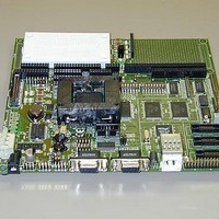
MPC566EVB
Description
KIT EVALUATION FOR MPC565/566
Manufacturer
Freescale Semiconductor
Specifications of MPC566EVB
Processor To Be Evaluated
MPC56x
Data Bus Width
32 bit
Interface Type
RS-232, Ethernet
Lead Free Status / RoHS Status
Contains lead / RoHS non-compliant


Freescale Semiconductor, Inc.
Installation And Setup
ation in the following text.
The ON jumper provides a constant enable to the VIGN signal so the Power Oak is enabled upon
power application. The ON option jumper may be removed to apply the VIGN signal externally
with a switch or other source. Basic operation of the VIGN signal is to apply +VIN to enable the
Power Oak supplies.
PWR jack connection provides power input from the supplied wall plug power source. Typical
input is +12VDC. The PWR jack provides a center positive terminal and ground outside sleeve.
The jack accepts 2.1mm inside x 5.5mm outside power plugs.
PWR Front View
TB1 Front View
2mm Center Pin, Positive Volt
GND +VIN VIGN
5.5mm Outer Ring, Ground
2.2.4 Selecting Terminal Baud Rate
The serial channel SCI0 of the MPC566 is used for serial communication and has a built in baud
rate generator. A number of baud rates can be programmed. On power-up or manual RESET, the
dBUG ROM monitor firmware configures the channel for 19200 baud. Once the dBUG ROM
monitor is running, a SET command may be issued to select any baud rate supported by the ROM
monitor. Refer to Chapter 3 for the discussion of this command.
2.2.5 The Terminal Character Format
The character format of the communication channel is fixed at power-up or RESET. The default
character format is 8 bits per character, no parity and one stop bit with no flow control. It is
neccessary to ensure that the terminal or PC is set to this format.
2.2.6 Connecting the Terminal
The board is now ready to be connected to a PC/terminal. Use the RS232 serial cable to connect
the PC/terminal to the MPC566EVB at COM-1. The cable has a 9-pin female D-sub terminal
connector at one end and a 9-pin male D-sub connector at the other end. Connect the 9-pin male
connector to connector COM-1 on the MPC566EVB board. Connect the 9-pin female connector
to one of the available serial communication channels normally referred to as COM1 (COM2, etc.)
on the PC running terminal emulation software (such as AxIDE, TeraTerm or Hyperterminal). The
connector on the PC/terminal may be either male 25-pin or 9-pin. It may be neccessary to obtain
a 25-pin-to-9-pin adapter to make this connection. If an adapter is required, refer to Figure 2-2
which shows the pin assignment for the 9-pin connector on the board.
Chapter 2. Initialization and Setup
2-5
For More Information On This Product,
Go to: www.freescale.com
Related parts for MPC566EVB
Image
Part Number
Description
Manufacturer
Datasheet
Request
R

Part Number:
Description:
Manufacturer:
Freescale Semiconductor, Inc
Datasheet:
Part Number:
Description:
Manufacturer:
Freescale Semiconductor, Inc
Datasheet:
Part Number:
Description:
Manufacturer:
Freescale Semiconductor, Inc
Datasheet:
Part Number:
Description:
Manufacturer:
Freescale Semiconductor, Inc
Datasheet:
Part Number:
Description:
Manufacturer:
Freescale Semiconductor, Inc
Datasheet:
Part Number:
Description:
Manufacturer:
Freescale Semiconductor, Inc
Datasheet:
Part Number:
Description:
Manufacturer:
Freescale Semiconductor, Inc
Datasheet:
Part Number:
Description:
Manufacturer:
Freescale Semiconductor, Inc
Datasheet:
Part Number:
Description:
Manufacturer:
Freescale Semiconductor, Inc
Datasheet:
Part Number:
Description:
Manufacturer:
Freescale Semiconductor, Inc
Datasheet:
Part Number:
Description:
Manufacturer:
Freescale Semiconductor, Inc
Datasheet:
Part Number:
Description:
Manufacturer:
Freescale Semiconductor, Inc
Datasheet:
Part Number:
Description:
Manufacturer:
Freescale Semiconductor, Inc
Datasheet:
Part Number:
Description:
Manufacturer:
Freescale Semiconductor, Inc
Datasheet:
Part Number:
Description:
Manufacturer:
Freescale Semiconductor, Inc
Datasheet: