STEVAL-TCS003V1 STMicroelectronics, STEVAL-TCS003V1 Datasheet - Page 54
STEVAL-TCS003V1
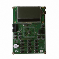
Manufacturer Part Number
STEVAL-TCS003V1
Description
BOARD DEMO EXPANDER STMPE2403
Manufacturer
STMicroelectronics
Specifications of STEVAL-TCS003V1
Main Purpose
Interface, GPIO Expander
Embedded
No
Utilized Ic / Part
STMPE2403
Primary Attributes
8/16/24-Bit 24-Port GPIO Expander over I2C
Secondary Attributes
3 8-Bit PWM Output for LEDs, Keyboard Matrix Scan, Special Key Support
Lead Free Status / RoHS Status
Lead free / RoHS Compliant
Other names
497-8206
Available stocks
Company
Part Number
Manufacturer
Quantity
Price


Keypad controller
12.8.1
12.8.2
12.8.3
54/63
Resistance
Maximum resistance between keypad output and keypad input, inclusive of switch
resistance, protection circuit resistance and connection, must be less than 3.2 KΩ
Using the keypad controller
It is not necessary to explicitly enable the internal pull-up and direction by configuring the GPIO control
registers. Once a GPIO is enabled for keypad function, its internal pull-up and direction is controlled
automatically.
The scanning of column inputs should then be enabled for those GPIO ports that are
configured as keypad inputs by writing ‘1’s to the corresponding bits in the KPC_col register.
If any of the first three column inputs is to be used as dedicated key input, the corresponding
bits in the KPC_ctrl_msb register should be set to ‘1’. The bits in the KPC_row_msb and
KPC_row_lsb registers should also be set correctly to enable the row output scanning for
the corresponding GPIO ports programmed as keypad outputs.
The scan count and de-bounce count should also be programmed into the keypad control
registers before enabling the keypad controller operation. To enable the keypad controller
operation, the Enable_KPC bit in the system control register must be set to ‘1’ to provide the
required clock signals. The keypad controller will then start its operation by setting the
SCAN bit in the KPC_ctrl_lsb register to ‘1’.
The keypad controller operation can be disabled by setting the SCAN bit back to ‘0’. To
further reduce the power consumption, the clock signals can be cut off from the keypad
controller by setting the Enable_KPC bit to ‘0’.
As long as there is any un-read key-press in the keypad controller buffer, the KPC interrupt
will always be asserted.
Ghost Key Handling
Ghost key is an inherent in keypad matrix that is not equipped with a diode at each of the
keys. While it is not possible to avoid ghost key occurrence, the STMPE2403 allow the
detection of possible ghost key by the capability of detecting 3 simultaneous key-presses in
the key matrix.
Ghost key is only possible if 3 keys are pressed and held down together in a keypad matrix.
If 3 keys are reported by STMPE2403 keypad controller, it indicates a potential ghost key
situation. The system may check for possibility of ghost key by analyzing the coordinates of
the 3 keys. If the 3 keys form 3 corners of a rectangle, it could be a ghost key situation.
Ghost key may also occur in the Special Function Keys. The keypad controller does not
attempt to avoid the occurrence of ghost keys. However, the system should be aware that if
more than one special function key is reported, then there is a possibility of ghost key.
STMPE2403
Related parts for STEVAL-TCS003V1
Image
Part Number
Description
Manufacturer
Datasheet
Request
R

Part Number:
Description:
BOARD EVAL FOR ST802RT1
Manufacturer:
STMicroelectronics
Datasheet:

Part Number:
Description:
EVAL BOARD 100 BASE T
Manufacturer:
STMicroelectronics
Datasheet:

Part Number:
Description:
BOARD ELECT FISCAL CASH REGISTER
Manufacturer:
STMicroelectronics
Datasheet:
Part Number:
Description:
BOARD EVAL FOR ST802RT1A
Manufacturer:
STMicroelectronics
Datasheet:

Part Number:
Description:
2 kW/100 V RF demonstration board for 3 T MRI based on the STAC4932B
Manufacturer:
STMICROELECTRONICS [STMicroelectronics]
Datasheet:

Part Number:
Description:
BOARD EVAL FOR MEMS SENSORS
Manufacturer:
STMicroelectronics
Datasheet:
Part Number:
Description:
EVALBOARD/STEVAL-ISV014V1
Manufacturer:
STMicroelectronics

Part Number:
Description:
BOARD EVAL FOR VACUUM CLEANER
Manufacturer:
STMicroelectronics
Datasheet:

Part Number:
Description:
KIT DEV STARTER ST10F276Z5
Manufacturer:
STMicroelectronics
Datasheet:

Part Number:
Description:
BOARD LED CTLR/DVR STLED316S
Manufacturer:
STMicroelectronics
Datasheet:
Part Number:
Description:
STMicroelectronics [RIPPLE-CARRY BINARY COUNTER/DIVIDERS]
Manufacturer:
STMicroelectronics
Datasheet:
Part Number:
Description:
STMicroelectronics [LIQUID-CRYSTAL DISPLAY DRIVERS]
Manufacturer:
STMicroelectronics
Datasheet:
Part Number:
Description:
BOARD EVAL FOR MEMS SENSORS
Manufacturer:
STMicroelectronics
Datasheet: