STEVAL-IFS002V1 STMicroelectronics, STEVAL-IFS002V1 Datasheet
STEVAL-IFS002V1
Specifications of STEVAL-IFS002V1
STEVAL-IFS002V1


Related parts for STEVAL-IFS002V1


STEVAL-IFS002V1 Summary of contents
Page 1
... Introduction This user manual describes the STEVAL-IFS002V1 STR9 MEMS extension hardware. As well as the block diagram and schematics of the extension, a bill of materials and assembly instructions are also included. The STR9 MEMS extension provides an STR9 dongle-based application with a MEMS sensor. MEMS (micro-electro-mechanical system) exploits the mechanical properties of silicon to create movable structures that, in the case of MEMS-based motion sensors, are able to sense motion (acceleration or vibration) in distinct directions ...
Page 2
Contents Contents 1 STR9 MEMS extension Block diagram . . . . . . . . . . . . . . . . . . . . . . . . . . 3 2 Schematics . . . ...
Page 3
UM0376 1 STR9 MEMS extension Block diagram This board is based on STR9 dongle. The main board features are the following: Analog MEMS: – LGA8 (LIS2L02AL, LIS2L06AL, LIS3L02AL, LIS3L06AL) – LGA14 (LIS302ALB) – LGA16 (LIS3L02AL3) Digital MEMS: – LGA14 (LIS302DL) ...
Page 4
Schematics 2 Schematics Figure 3. STR9 dongle schematics P77 NC Voutz 15 7 P42mems P45 Vdd RES 8 4 RES(Vdd) Voutx 14 7 4/17 RDY/INT GND P54 1 14 SDO Vdd SSP0_MISO ...
Page 5
UM0376 3 MEMS footprints 3.1 LGA8 package Figure 4. MEMS footprint (LGA8 package) Table 1. Mechanical data Xm Height Ys Xs Width Symbol Height Width MEMS footprints Ym Yd ai14147 Dimension Unit 0.79 mm 1.35 ...
Page 6
MEMS footprints 3.2 LGA14 package Figure 5. MEMS footprint (LGA14 package) Height Table 2. Mechanical data 6/ Width Symbol Height Width ai14148 Dimension Unit 0.64 mm 0.975 mm 2.0 mm ...
Page 7
UM0376 3.3 LGA16 (D) package Figure 6. MEMS footprint (LGA16 (D) package) Height Table 3. LGA16 (D) mechanical data Symbol Xm Ym Height Width Width MEMS footprints ai14149 Dimension 0.65 ...
Page 8
MEMS footprints 3.4 LGA16 (A) package Figure 7. MEMS footprint (LAG16 (A) package) Table 4. Mechanical data Symbol Height Width 8/17 Xm Height Ys Xs Width ai14150 Dimension 0.64 0.975 2 ...
Page 9
UM0376 3.5 QFN28 package Figure 8. MEMS footprint (QFN28 package) Height 1. Draft only. Not all the 28 pins are shown. Table 5. Mechanical data Symbol Height Ys Xs Width Width MEMS footprints Xm ...
Page 10
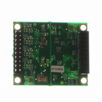
PCB layout 4 PCB layout Figure 9. Top view Figure 10. Bottom view 10/17 UM0376 ...
Page 11
UM0376 5 Bill of materials and assembly instructions Table 6 to Table 15 provide additional information on assembly. 5.1 Assembly information for analog MEMS 1. When U10 LD2980CMxx is not assembled use R100 instead. For low voltage MEMS use a ...
Page 12
Bill of materials and assembly instructions 5.3 Assembly information for serial memory 1. When U13 LD2980CMxx is not assembled, use R130 instead. All mentioned memories should be able to operate on 3.3 V. Use a voltage regulator for low voltage ...
Page 13
UM0376 (1) Table 9. Analog MEMS Label Comment CN5 ANALOG_CON U1 LIS302ALB C10 100 nF C11 2.2 µF U2 LIS3/2L06/2AL C20 100 nF C21 2.2 µF U3 LIS3LV02AL3 C30 100 nF C31 2.2 µ default, the LIS3/2L06/2AL is ...
Page 14
Bill of materials and assembly instructions (1) Table 11. Memory Label Comment M95xx/M25xx/ U7 M34xx C70 10 nF C71 default, the memory is not assembled. Table 12. Operational amplifier X-axe for analog MEMS Label Comment U80 ...
Page 15
UM0376 Table 15. Operational amplifier Xyz-axe for analog MEMS Label Comment U83 TS507ILT R83 0 Ω R90 10 k Ω R91 10 k C83 100 nF C87 default, the amplifier is not assembled. Bill of materials ...
Page 16
Revision history 6 Revision history Table 16. Document revision history Date 19-Jan-2007 24-May-2007 12-Nov-2007 16/17 Revision 1 Initial release. Figure 3: STR9 dongle Figure 10: Bottom view Stabilisator replaced by voltage regulator in the whole document. 2 MEMS footprint figures ...
Page 17
... UM0376 Information in this document is provided solely in connection with ST products. STMicroelectronics NV and its subsidiaries (“ST”) reserve the right to make changes, corrections, modifications or improvements, to this document, and the products and services described herein at any time, without notice. All ST products are sold pursuant to ST’s terms and conditions of sale. ...