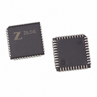
Z86E4000ZDV Zilog, Z86E4000ZDV Datasheet - Page 36

Z86E4000ZDV
Manufacturer Part Number
Z86E4000ZDV
Description
44 PIN PLCC ADAPTER
Manufacturer
Zilog
Datasheet
1.Z86E4001ZDV.pdf
(64 pages)
Specifications of Z86E4000ZDV
Convert From (adapter End)
40-Pin DIP ZIF Socket
Convert To (adapter End)
44-PLCC Plug
For Use With/related Products
Zilog Emulators/Programmers
Lead Free Status / RoHS Status
Contains lead / RoHS non-compliant
Other names
269-2015
FUNCTIONAL DESCRIPTION (Continued)
Z86E30/E31/E40
Z8 4K OTP Microcontroller
General-Purpose Registers (GPR). These registers are
undefined after the device is powered up. The registers
keep their last value after any reset, as long as the reset
occurs in the V
register R254 is general-purpose on Z86E30/E31. R254
and R255 are set to 00H after any reset or STOP-Mode
Recovery.
RAM Protect. The upper portion of the RAM's address
spaces 80H to EFH (excluding the control registers) can
be protected from reading and writing. This option can be
selected during the EPROM Programming Mode. After this
option is selected, the user can activate this feature from
the internal EPROM. D6 of the IMR control register (R251)
is used to turn off/on the RAM protect by loading a 0 or 1,
respectively. A “1” in D6 indicates RAM Protect enabled.
RAM Protect is not available on the Z86E31.
Stack. The Z86E40 external data memory or the internal
register file can be used for the stack. The 16-bit Stack
Pointer (R254–R255) is used for the external stack, which
can reside anywhere in the data memory for ROMless
mode, but only from 4096 to 65535 in ROM mode. An 8-bit
Stack Pointer (R255) is used for the internal stack on the
Z86E30/E31/E40 that resides within the 236 general-pur-
pose registers (R4–R239). SPH (R254) can be used as a
general-purpose register when using internal stack only.
R254 and R255 are set to 00H after any reset or Stop-
Mode Recovery.
36
CC
voltage-specified operating range. The
P R E L I M I N A R Y
Counter/Timers. There are two 8-bit programmable
counter/timers (T0 and T1), each driven by its own 6-bit
programmable prescaler. The T1 prescaler is driven by in-
ternal or external clock sources; however, the T0 prescaler
is driven by the internal clock only (Figure 27).
The 6-bit prescalers can divide the input frequency of the
clock source by any integer number from 1 to 64. Each
prescaler drives its counter, which decrements the value
(1 to 256), that has been loaded into the counter. When the
counter reaches the end of count, a timer interrupt request,
IRQ4 (T0) or IRQ5 (T1), is generated.
The counters can be programmed to start, stop, restart to
continue, or restart from the initial value. The counters can
also be programmed to stop upon reaching zero (single
pass mode) or to automatically reload the initial value and
continue counting (modulo-n continuous mode).
The counters, but not the prescalers, can be read at any
time without disturbing their value or count mode. The
clock source for T1 is user-definable and can be either the
internal microprocessor clock divided by four, or an exter-
nal signal input through Port 3. The Timer Mode register
configures the external timer input (P31) as an external
clock, a trigger input that can be retriggerable or non-retrig-
gerable, or as a gate input for the internal clock. Port 3 line
P36 serves as a timer output (T
or the internal clock can be output. The counter/timers can
be cascaded by connecting the T0 output to the input of
T1.
OUT
) through which T0, T1,
DS97Z8X0502
Zilog


