101-1053 Rabbit Semiconductor, 101-1053 Datasheet - Page 40
101-1053
Manufacturer Part Number
101-1053
Description
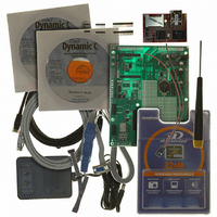
KIT DEV RABBITCORE RCM3365 US
Manufacturer
Rabbit Semiconductor
Series
RabbitCore 3000r
Type
MPU Core Moduler
Datasheet
1.20-101-1051.pdf
(164 pages)
Specifications of 101-1053
Contents
RabbitCore Module, Dev. Board, AC Adapter, Cable and Dynamic C® CD-Rom
Processor To Be Evaluated
RCM3365
Interface Type
Ethernet
Maximum Operating Temperature
+ 70 C
Operating Supply Voltage
3.15 V to 3.45 V
For Use With/related Products
RCM3365
Lead Free Status / RoHS Status
Lead free by exemption / RoHS compliant by exemption
Other names
316-1074


4.2 Serial Communication
The RCM3365/RCM3375 does not have any serial transceivers directly on the board.
However, a serial interface may be incorporated into the board the RCM3365/RCM3375
is mounted on. For example, the Prototyping Board has RS-232 and RS-485 transceiver
chips.
4.2.1 Serial Ports
There are six serial ports designated as Serial Ports A, B, C, D, E, and F. All six serial
ports can operate in an asynchronous mode up to the baud rate of the system clock divided
by 8. An asynchronous port can handle 7 or 8 data bits. A 9th bit address scheme, where
an additional bit is sent to mark the first byte of a message, is also supported.
Serial Port A is normally used as a programming port, but may be used either as an asyn-
chronous or as a clocked serial port once the RCM3365/RCM3375 has been programmed
and is operating in the Run Mode.
Serial Port B is available on the RCM3365/RCM3375, and may be used as an
asynchronous port. PB0 is used to enable Dynamic C to detect whether the xD-Picture
Card is installed. If the card detect is not needed by your application program, you may
remove R96 (see Figure A-5) to disable the xD-Picture Card detect, and then use Serial
Port B as a clocked serial port.
Serial Ports C and D can also be operated in the clocked serial mode. In this mode, a clock
line synchronously clocks the data in or out. Either of the two communicating devices can
supply the clock.
Serial Ports E and F can also be configured as HDLC serial ports. The IrDA protocol is
also supported in SDLC format by these two ports.
4.2.2 Ethernet Port
Figure 8 shows the pinout for the RJ-45 Ethernet port (J2). Note that some Ethernet
connectors are numbered in reverse to the order used here.
Three LEDs are placed next to the RJ-45 Ethernet jack, one to indicate an Ethernet link
(
The RJ-45 connector is shielded to minimize EMI effects to/from the Ethernet signals.
34
LINK
) one to indicate Ethernet activity (
Figure 8. RJ-45 Ethernet Port Pinout
ETHERNET
ACT
), and one to indicate the 10/100Base-T speed.
RabbitCore RCM3365/RCM3375
Related parts for 101-1053
Image
Part Number
Description
Manufacturer
Datasheet
Request
R

Part Number:
Description:
KIT DEV STANDARD RCM5700
Manufacturer:
Rabbit Semiconductor
Datasheet:

Part Number:
Description:
BL4S200 TOOL KIT
Manufacturer:
Rabbit Semiconductor
Datasheet:


Part Number:
Description:
KIT DEV FOR BL2500 COYOTE
Manufacturer:
Rabbit Semiconductor
Datasheet:

Part Number:
Description:
Microcontroller Modules & Accessories Keypad/Display Unit 5V Panel Mount
Manufacturer:
Rabbit Semiconductor

Part Number:
Description:
Single Board Computers 24VDC/110 Power Supp
Manufacturer:
Rabbit Semiconductor
Part Number:
Description:
MODULE RABBITCORE RCM3720
Manufacturer:
Rabbit Semiconductor
Datasheet:
Part Number:
Description:
MODULE RABBITCORE RCM3220
Manufacturer:
Rabbit Semiconductor
Datasheet:
Part Number:
Description:
MODULE RABBITCORE RCM3210
Manufacturer:
Rabbit Semiconductor
Datasheet:
Part Number:
Description:
COMPUTER SGL-BOARD OP6600 W/SRAM
Manufacturer:
Rabbit Semiconductor
Datasheet:
Part Number:
Description:
COMPUTER SGL-BD BL2000 SRAM/FLSH
Manufacturer:
Rabbit Semiconductor