AD8220-EVALZ Analog Devices Inc, AD8220-EVALZ Datasheet - Page 8
AD8220-EVALZ
Manufacturer Part Number
AD8220-EVALZ
Description
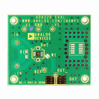
BOARD EVAL FOR AD8220ARMZ
Manufacturer
Analog Devices Inc
Specifications of AD8220-EVALZ
Design Resources
Fully Isolated Input Module Based on AD7793, ADuM5401, and a High Performance In-Amp (CN0067)
Channels Per Ic
1 - Single
Amplifier Type
Instrumentation
Output Type
Single-Ended, Rail-to-Rail
Slew Rate
2 V/µs
-3db Bandwidth
1.5MHz
Current - Output / Channel
15mA
Operating Temperature
-40°C ~ 85°C
Current - Supply (main Ic)
750µA
Voltage - Supply, Single/dual (±)
4.5 V ~ 36 V, ±2.25 V ~ 18 V
Board Type
Fully Populated
Utilized Ic / Part
AD8220
Silicon Manufacturer
Analog Devices
Application Sub Type
JFET Input Instrumentation Amplifier
Kit Application Type
Amplifier
Silicon Core Number
AD8220
Kit Contents
Board
Lead Free Status / RoHS Status
Lead free / RoHS Compliant
Other names
AD8220-EVAL
AD8220-EVAL
AD8220-EVAL


AD8220
ABSOLUTE MAXIMUM RATINGS
Table 3.
Parameter
Supply Voltage
Power Dissipation
Output Short-Circuit Current
Input Voltage (Common Mode)
Differential Input Voltage
Storage Temperature Range
Operating Temperature Range
Lead Temperature (Soldering 10 sec)
Junction Temperature
θ
Package Glass Transition Temperature
ESD (Human Body Model)
ESD (Charge Device Model)
ESD (Machine Model)
1
2
Assumes the load is referenced to midsupply.
Temperature for specified performance is −40°C to +85°C. For performance
to 125°C, see the Typical Performance Characteristics section.
JA
(4-Layer JEDEC Standard Board)
2
Rating
±18 V
See Figure 3
Indefinite
±Vs
±Vs
−65°C to +125°C
−40°C to +125°C
300°C
140°C
135°C/W
140°C
4 kV
1 kV
0.4 kV
1
Rev. B | Page 8 of 28
Stresses above those listed under Absolute Maximum Ratings
may cause permanent damage to the device. This is a stress
rating only; functional operation of the device at these or any
other conditions above those indicated in the operational
section of this specification is not implied. Exposure to absolute
maximum rating conditions for extended periods may affect
device reliability.
Figure 3 shows the maximum safe power dissipation in the
package vs. the ambient temperature for the MSOP on a 4-layer
JEDEC standard board. θ
ESD CAUTION
Figure 3. Maximum Power Dissipation vs. Ambient Temperature
2.00
1.75
1.50
1.25
1.00
0.75
0.50
0.25
0
–40
–20
0
AMBIENT TEMPERATURE (°C)
JA
values are approximations.
20
40
60
80
100
120
Related parts for AD8220-EVALZ
Image
Part Number
Description
Manufacturer
Datasheet
Request
R

Part Number:
Description:
AD8220/1/6/8/9 MSOP Pkg Eval Bd
Manufacturer:
Analog Devices Inc
Datasheet:

Part Number:
Description:
Single Supply, Rail to Rail Low Power FET-Input Op Amp
Manufacturer:
Analog Devices
Datasheet:

Part Number:
Description:
±1.7g Dual-Axis IMEMS Accelerometer Evaluation Board
Manufacturer:
Analog Devices Inc
Datasheet:
Part Number:
Description:
Inertial Sensor Evaluation System
Manufacturer:
Analog Devices Inc
Datasheet:
Part Number:
Description:
Manufacturer:
Analog Devices Inc
Datasheet:
Part Number:
Description:
Manufacturer:
Analog Devices Inc
Datasheet:
Part Number:
Description:
Manufacturer:
Analog Devices Inc
Datasheet:
Part Number:
Description:
Manufacturer:
Analog Devices Inc
Datasheet:
Part Number:
Description:
Manufacturer:
Analog Devices Inc
Datasheet:
Part Number:
Description:
Manufacturer:
Analog Devices Inc
Datasheet:
Part Number:
Description:
Manufacturer:
Analog Devices Inc
Datasheet:
Part Number:
Description:
Manufacturer:
Analog Devices Inc
Datasheet:
Part Number:
Description:
Manufacturer:
Analog Devices Inc
Datasheet: